Home » Products » Steel Structures » Substation Steel Gantries

Substation Gantry Manufacturer

Columns and crossmembers with coordinated attachment points, bases and field joints

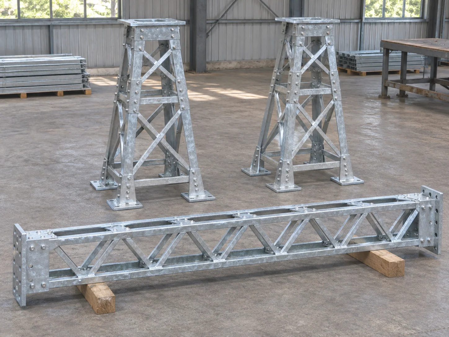
We fabricate substation gantry steel from the utility’s released arrangement and connection drawings. Columns, crossmembers, bracing and attachment plates are grouped by structure mark, with base and conductor-attachment datums carried into the shop details. The supplied package is the identified steelwork and hardware, separate from electrical apparatus and foundations.
Steel package
Columns, crossmembers and braces
Interfaces
Attachment and foundation datums
Finish route
Specified galvanizing or paint
Order unit
Structure marks and BOM

Gantry members and their controlling interfaces

ColumnsSection, base plane, connection ends and attachment elevations
CrossmembersSpan geometry, conductor attachment points and field splices
BracingMember marks, end connections and structure orientation
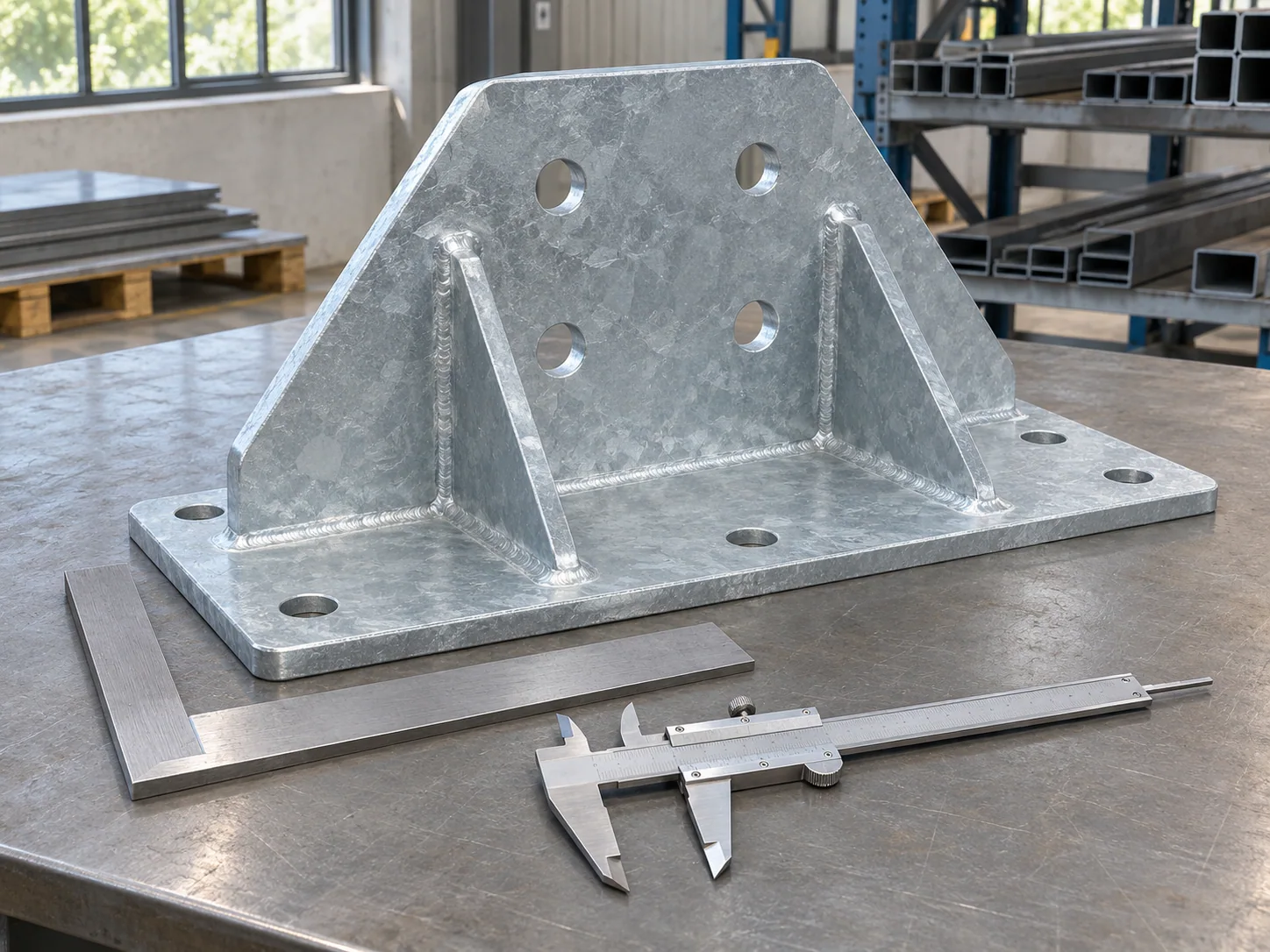
Base platesAnchor pattern, plate orientation and leveling/bearing detail
Attached steelInsulator or other scheduled mounting plates and brackets
Loose hardwareSpecified field bolts and separate anchor/mounting hardware scope

Galvanizing reference for mixed gantry components

A gantry can combine structural shapes, plate and tube. ASTM A123 coating requirements distinguish material category as well as measured steel thickness.

Measured steel thickness (mm)Material categoryMinimum average coating reference (µm)
8Structural shapes100
8Plate75
8Pipe and tubing75
20Structural shapes100
20Plate100
20Pipe and tubing75

No matching specification. Clear the search to see every row.

Scroll sideways to see every column.

ASTM A123 material-category reference at the selected measured steel thicknesses, cross-checked with American Galvanizers Association guidance. Each supplied component uses its applicable category and thickness; separate hardware follows its own finish specification. Project exposure and the protection system govern the service-life assessment.

Utility interfaces and steelwork boundaries

Attachment reactions belong to defined points

Conductor and equipment loads are referenced to their actual attachment coordinates. Their direction, eccentricity and governing condition stay with the structural design instead of being reduced to a single unspecified frame load.

Bases match the foundation datum

Anchor centers, plate orientation and finished support level define the steel-to-foundation interface. The selected base arrangement identifies grout, leveling and anchor-hardware requirements.

Steel supply is separate from the electrical installation

The supplied steelwork and listed hardware form an identified package. Insulators, conductors, earthing arrangements and electrical apparatus have their own design, purchase and installation scopes.

Attachment locations and galvanized member detailing

Member axes and fixing planes

Attachment plates are located from the structure datums and their required fixing planes. Plate thickness and stand-off can place the final attachment away from a crossmember centerline, which is retained in the shop dimensions.

Bolted breaks for the shipping envelope

Crossmember and column breaks follow the released structural connection. The shipping assembly retains orientation, mating flange or plate marks and the field bolt groups for that joint.

Vent and drain details before galvanizing

Hollow members and closed details need suitable access for the galvanizing route. The accepted vent and drain locations remain part of the fabrication drawing and are coordinated with caps, bases and attachment plates.

Grounding lugs and later attachments

Required steel lugs and drilled fixing points are itemized from the utility detail. Adding an attachment after finish changes both the local steel detail and its protection, so it remains a controlled scope item.

Gantry packages for switchyards and line entries

New structure schedules

Each gantry mark connects columns, crossmembers and bracing to its foundation and attachment arrangement. Similar-looking structures with different conductor points retain separate marks.

Extensions to retained steelwork

The retained structure, field survey and accepted extension design establish the new pieces and their connection geometry. The fabrication details carry those mating interfaces into the extension package.

Attachment and base geometry checks

Gantry hole-pattern inspection

Finished mounting positions

Checks locate attachment holes and bearing faces from the released structure axes. End-plate orientation and assembled dimensions are checked in the stated shop arrangement.

Hollow sections and galvanized surfaces

The inspection plan covers required vent/drain details, welds and protection. Finished holes and joint contact surfaces remain accessible for the intended fastening set.

Member and hardware register

Material and inspection records follow the gantry marks. Anchor rods, field bolts and apparatus mounting bolts remain separate groups with their own included quantities.

Gantry steelwork records

Structure drawing revisionAttachment/base dimensionsRequired weld checksFinish measurementsField-joint hardware list

Structure-based pricing and shipping groups

Steel and mounting scope separated

Our quotation lists gantry members, attached plates and field hardware. Foundations, electrical apparatus, insulators and any separate anchor-rod supply are identified independently.

Members supported at agreed points

Crossmembers and columns are restrained on suitable dunnage with protection around mounting plates and galvanized faces. Loose braces and hardware travel in linked receiving groups.

One receiving list per structure group

The packing register reconciles shipping pieces and boxed connection sets to the structure mark. Special attachment revisions stay distinguishable from repeated standard details.

Substation Steel Gantries purchasing questions

Which drawings define the gantry steel order?

The released utility arrangement and structural details identify attachment geometry, reactions, clearances, foundations and environmental actions. They define the steel package associated with the project’s voltage class.

Are insulators included with their steel mounting plates?

They are separate items unless the offer explicitly includes them. The mounting plate drawing identifies the interface, while the insulator has its own electrical and mechanical specification.

Can anchor holes be changed after the base plate is galvanized?

An accepted hole revision includes its base-connection design and local protection-repair detail. Those requirements establish the permitted work and its final acceptance.

How is galvanizing specified across mixed gantry components?

ASTM A123 uses material category and measured steel thickness to determine the applicable requirement. Plate, structural shapes and pipe/tube retain their respective categories; hardware follows its specified finish standard.

Can conductor brackets be supplied loose instead of welded on?

The attachment route must match the accepted structural detail. A loose bolted bracket and a welded plate have different connections and hardware; the quotation identifies whichever assembly is released.

How is grounding-related supply identified?

The offer lists any steel grounding lugs or attachment points in the fabricated package. Conductors, clamps, bonding arrangements and installation are separate electrical-design and purchase items.

Get a gantry steelwork quote

Send the gantry arrangement, member BOM, attachment and base details with quantities, material, finish and destination. Include the required utility records and hardware boundary for a structure-by-structure fabrication offer.

Metdax
Get a quote
Search Metdax

Language

Get a factory quote

Send your specifications or attach a material list.

Substation Steel Gantries

Your information is used to respond to this inquiry. Privacy policy

sales@metdax.com

+86 177 7599 6440