Home » Products » Steel Structures » Bridge Girder Fabrication

Bridge Girder Fabricator

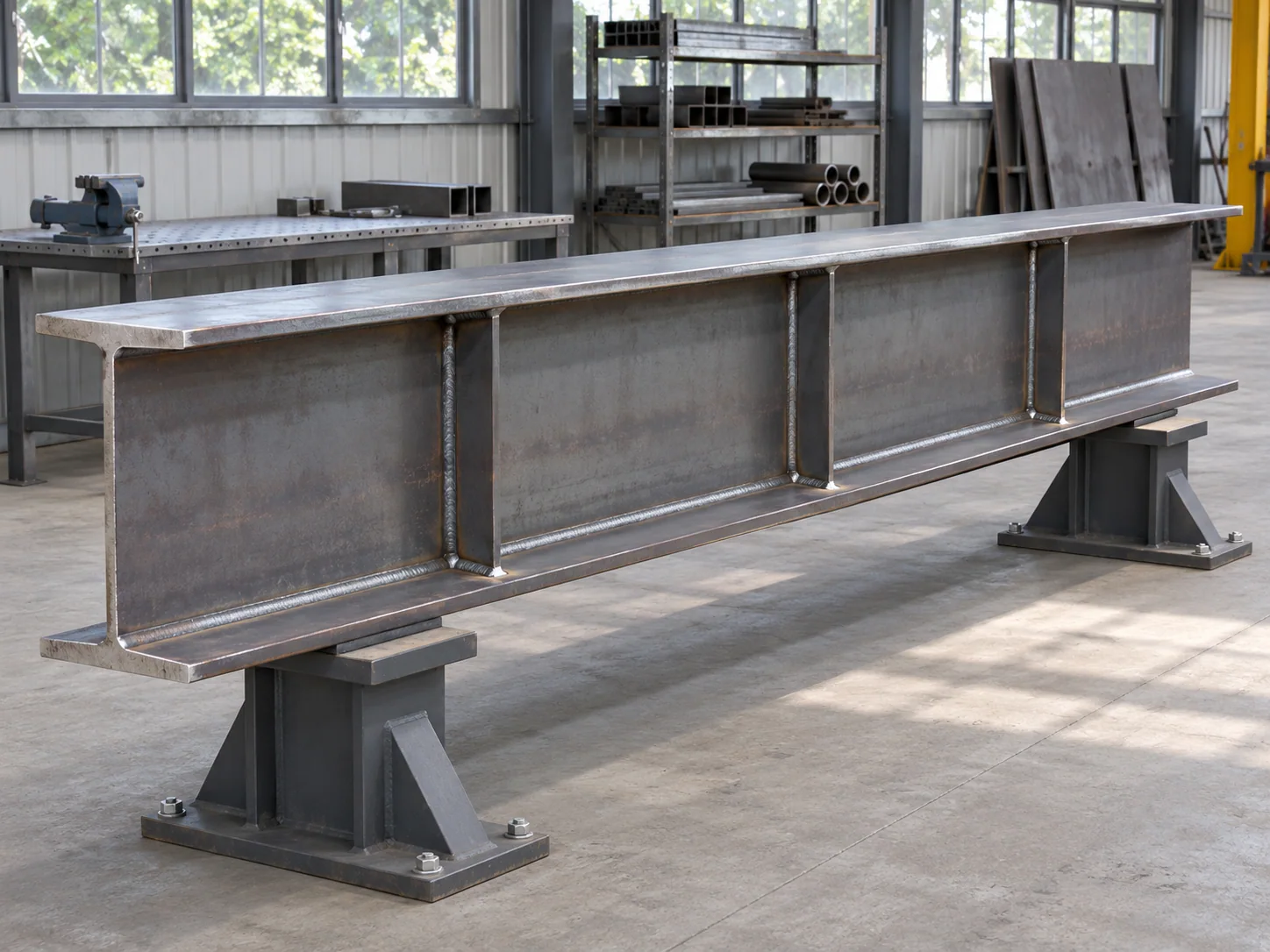
Welded I-girder segments with coordinated camber, bearing details and field splices

We fabricate welded steel I-girder segments from the released bridge drawings. Web and flange plates, bearing stiffeners and connection pieces retain their individual material identities through assembly. Shop work, field-splice interfaces and matching loose pieces are listed against each shipping-segment mark.
Primary form
Welded plate I-girders
Geometry
Released section and camber
Delivery unit
Identified shipping segments
Origin
China

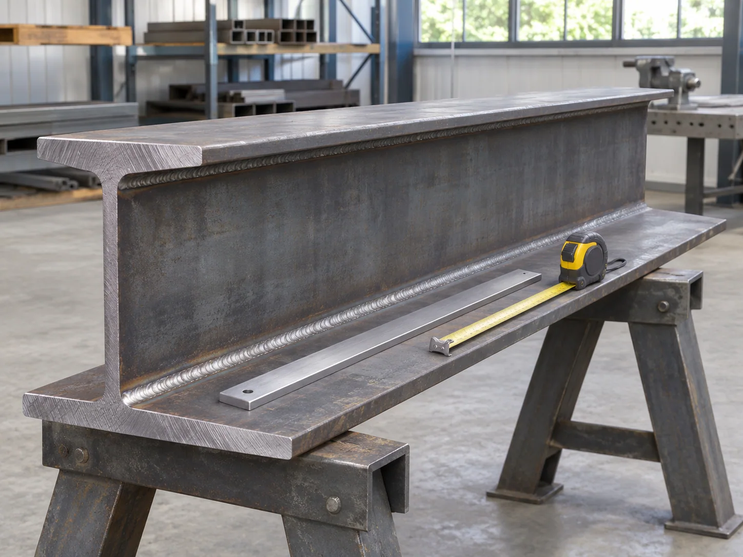
The fabricated girder assembly

Girder sectionWeb depth/thickness and separate upper/lower flange dimensions
AlignmentStraight, curved or other issued geometry identified on the member detail
CamberSpecified ordinates, reference condition and measurement datums
Attached platesBearing stiffeners, connection plates and other scheduled details
SplicesShop plate splices and field assembly joints distinguished
FinishGirder, joint surfaces and permitted repair scope identified separately
ShipmentSegment length, handling envelope and loose connection parts

Theoretical plate mass for girder takeoffs

Plate thickness changes the mass allowance for webs, flanges and stiffeners. The values below give mass per square meter of flat steel before holes, weld metal, coatings or cutting loss.

Plate thickness (mm)Theoretical steel mass (kg/m²)
647.10
862.80
1078.50
1294.20
16125.60
20157.00

No matching specification. Clear the search to see every row.

Scroll sideways to see every column.

Derived plate takeoff reference: mass/area = thickness in meters × 7,850 kg/m³ steel density. The released girder BOM supplies the actual plate dimensions and materials. Girder unit mass, shipping gross mass and structural design use their respective assembly, packing and design bases.

Bridge material and fabrication requirements

Grade on each plate item

The project material callout remains with the web, flanges and stiffeners, including specified toughness requirements. Each ASTM A572 or A709 designation retains its own material and acceptance requirements on the girder schedule.

Welds identified by function

Web-to-flange welds, plate butt splices and attachment welds have different locations and examination requirements. The joint schedule identifies the governing welding specification and required procedure or qualification records.

Project source approval

We supply China-origin fabricated components for projects that accept that source. Required fabricator qualifications, origin provisions and project approvals are identified with the purchaser before order acceptance.

Plate assembly, camber and bearing fit

Web and flange splices located independently

The released detail fixes the plate-splice locations and their relationship to stiffeners, holes and attachments. Moving a splice to use a convenient plate length changes the fabricated member and needs acceptance before production.

Camber measured in the stated condition

The camber diagram identifies reference points and the member condition used for measurement. Shop support positions and self-weight can affect the measured shape; the record keeps those conditions with the ordinates.

Bearing stiffeners and connection plates

Bearing contact, flange clearance and cross-frame attachments use their own fit details. Stiffener ends and weld access are prepared to preserve the specified bearing surfaces, clearances and attachment locations.

Field joints prepared for assembly

Web and flange splice interfaces retain the released hole pattern and matched-piece identity. Shop preassembly or other fit-up checks are included where the order requires them, with the inspected condition recorded.

Girder segments for new and replacement steelwork

New bridge girder lines

Member and shipping-piece marks connect the fabrication drawings to the erection sequence. Cross-frames, bearings and deck attachments have their own interface references within that girder line.

Replacement segments

The retained steel geometry and approved repair design govern replacement ends and splice arrangements. Surveyed dimensions are distinguished from nominal historical drawings where the project requires a site fit.

Girder geometry and joint acceptance

Girder geometry inspection

Complete assembly geometry

Checks cover flange position, web alignment, member length and the required camber condition. The dimensional record relates the actual measured locations to the drawing datums.

Weld and material records

Material identity follows the plate items into the assembly. Required weld-examination records identify the actual joint, inspection method and acceptance criteria.

End and bearing interfaces

Splice holes, bearing contact and attached connection pieces are checked before finish or dispatch as required by the inspection plan. Any accepted deviation retains its affected member and revision.

Girder fabrication records

Plate and heat mapWeld and examination registerCamber/geometry reportSplice and bearing checksFinish and shipping-piece register

Segment prices and transport preparation

Steelwork and fit-up priced explicitly

Our offer separates fabricated girder segments, loose joint items, required shop assembly checks and protection scope. The price basis states whether it uses finished member mass or another agreed measure.

Supports follow the shipping arrangement

Dunnage and restraints support the segment at the agreed locations. Flange projections, connection plates and prepared joint faces are protected from concentrated packing contact.

Segments arrive in the erection groups

The shipping list retains member orientation, piece marks, mass and loose splice-item counts. A revised transport break is carried into the segment drawing and receiving register.

Bridge Girder Fabrication purchasing questions

How are girder shipping breaks selected?

The accepted splice design and transport plan establish each break. Its joint and fabrication details are carried into the shipping-segment drawing and loose splice-item schedule.

Which setup is used to measure girder camber?

The drawing and inspection plan state the supports, girder orientation and reference points. Camber is recorded under that condition so its self-weight and support basis matches the required geometry.

Are shear studs included with a fabricated girder?

Studs and attachment work are included as listed offer items. The girder/deck interface schedule identifies stud type, positions, welding responsibility and any site-installed items.

Does weathering steel mean every surface is left uncoated?

The project protection detail identifies painted and exposed zones, including bearings, joints and drainage-sensitive areas. Those requirements define the surface-treatment scope for the selected weathering-steel grade.

Can plate thickness be increased to avoid a material shortage?

A proposed plate change is submitted for material and detail acceptance. The review covers member mass, geometry, welds and connection clearances before the revised plate enters fabrication.

Does the fabrication quotation include erection or temporary bracing?

The offer identifies shop-fabricated steel and the specifically listed services. Site erection, temporary restraints and lifting engineering remain separate unless expressly included in the contract.

Get a girder-segment fabrication offer

Send the girder drawings and BOM with camber data, splice and bearing details, material/test requirements and proposed shipping breaks. Include quantities, finish, accepted origin and destination for an itemized fabrication offer.

Metdax
Get a quote
Search Metdax

Language

Get a factory quote

Send your specifications or attach a material list.

Bridge Girder Fabrication

Your information is used to respond to this inquiry. Privacy policy

sales@metdax.com

+86 177 7599 6440