Home » Products » Ground Screws & Helical Piles » Helical Piles

Helical Pile Manufacturer

Drawing-based round-shaft and square-bar components for foundation orders

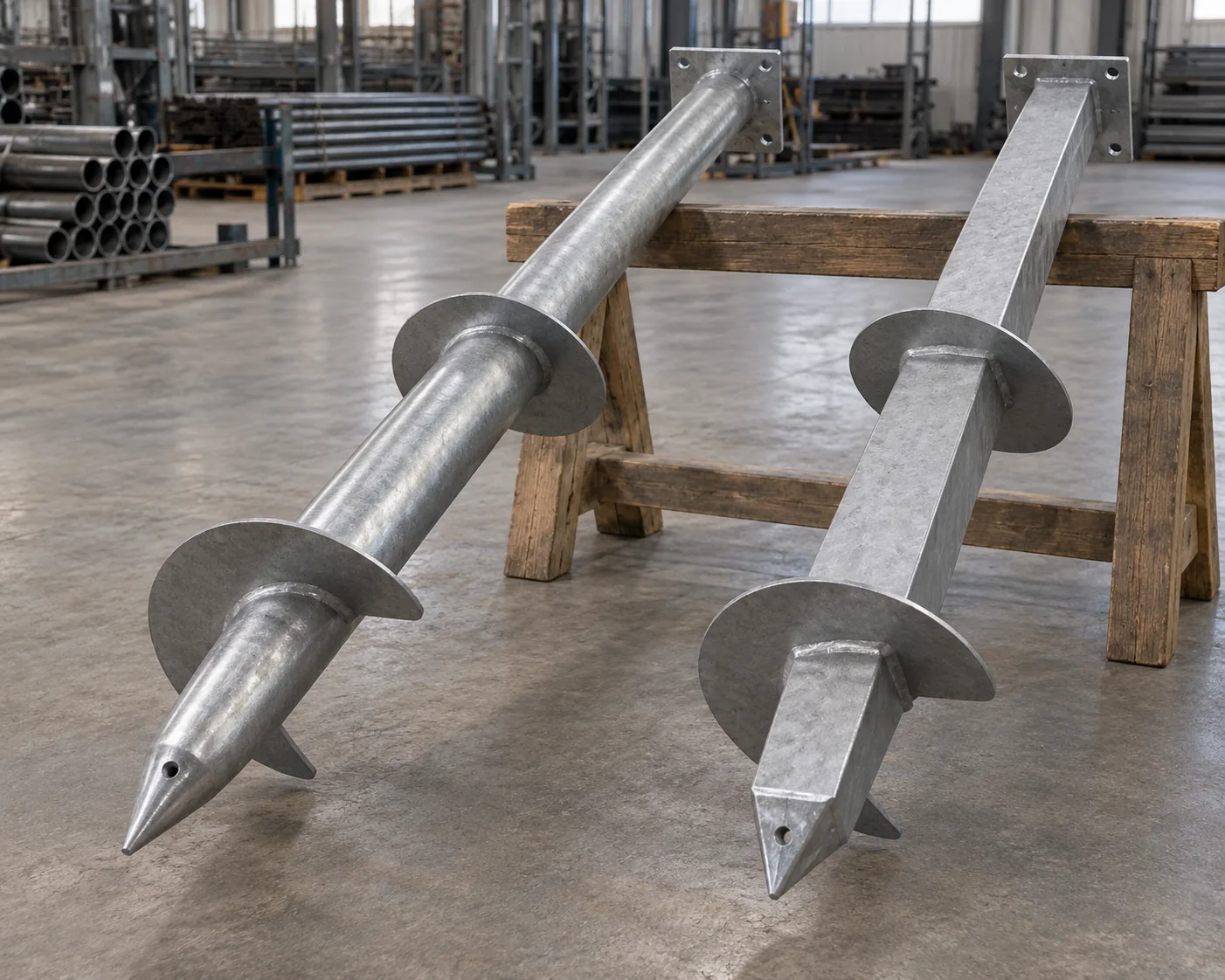
Helical pile leads use discrete bearing plates on a round tubular or solid square-bar shaft. We fabricate the lead, matching extensions and pile top to the pile drawings, including helix diameter, pitch and spacing, coupling geometry and joint hardware.

Shaft options
Round tube or solid square bar
Lead geometry
Discrete formed helices
Connections
Matched couplings and hardware
Order basis
Accepted pile schedule

Lead sections, extensions and pile tops

The lead carries the bearing plates. Extensions add shaft length above it, while the cap or bracket connects the pile to the supported foundation or frame. Couplings and fastening parts join those components.

Drawing-defined components in a helical pile order
Order itemSupplied steel or hardwareDetail that defines the item
Lead sectionShaft, pilot tip, formed helix plates and prepared upper connectionShaft section, helix arrangement and lead drawing
Extension sectionPlain shaft or specified flighted extension with prepared endsSection length, added length and connection revision
Coupling and joint hardwareSpecified sleeve or coupling with counted bolts and nutsMating shafts, engagement, holes and fastener schedule
Pile topFabricated cap, bracket or other drawn load-transfer connectionPile-shaft fit and supported foundation or frame interface
Supply recordsMaterial, fabrication, finish and identification recordsAgreed inspection plan and component marks

Scroll sideways to see every column.

We supply fabricated steel components to the pile drawings. The project’s foundation design and required system approval establish the configuration; installation and field acceptance use the project’s specified criteria.

Shaft sections and helix arrangements

Shaft section, helix count and plate spacing define the lead configuration. These dimensions are considered together with the pilot and upper connection.

Round tube or solid square bar

A round shaft is specified by outside diameter, wall thickness and material. A square-bar shaft uses its bar dimensions and material, with the matching end connection. The foundation design also considers stiffness, unsupported length and the required actions; shaft shape alone does not determine which configuration serves the project.

Helix diameter, pitch and sequence

Each bearing plate has its own diameter, thickness and formed pitch. The drawing locates the plates along the shaft and fixes their sequence from the pilot upward. A lead with several helices retains that complete schedule, including the spacing and relationship between plates of different diameters.

Pilot and lead datums

The pilot tip, first helix and upper connection are located from common drawing datums. Total lead length alone does not locate the bearing plates or define the prepared connection.

Finish for shafts, helices and connections

Buried and exposed steel

The corrosion specification addresses the buried shaft and bearing plates as well as the exposed pile top. Soil exposure, groundwater and the required corrosion allowance belong to that durability basis. The steel thickness and protection route are retained together in the fabrication order.

Finish after plate fabrication

Bare steel, hot-dip galvanizing or a specified paint system follows the accepted component schedule. Formed plates and their welds are included in the finish scope for the completed lead. A different treatment at the top or exposed zone is identified by its coverage rather than assumed from the shaft description.

Coupling clearance and hardware

The coating specification accounts for the surfaces inside a coupling and the holes used for its through-bolts. Finished engagement and seating must retain the connection detail. Bolts and nuts carry their own finish requirements, including the specified treatment of contact faces and any damaged coating.

Extension joints and useful added length

Match the complete joint

The coupling fits the actual shaft section and prepared end. Engagement, aligned holes and bolt grip follow the same connection drawing, with the specified bolt grade, length, nuts and shear-plane detail. Equal shaft diameter or a similar sleeve appearance does not establish an interchangeable joint.

Overall and added extension length

An extension’s overall length includes the part that engages in its joint. Its useful added length is the increment contributed to the assembled pile after that engagement. Both dimensions are identified for the selected extension, so an order for additional depth can use the correct component lengths and counts.

Plain or flighted extension sections

Plain extensions continue the shaft above the lead’s bearing plates. Where the design includes helices on an extension, that section has a separate drawing and plate schedule. Its orientation and connection retain the specified arrangement of the assembled pile, rather than treating it as an ordinary plain extension.

Pile materials and AC358 geometry references

US system requirements can include ICC-ES AC358. Its Table 3 gives geometry and installation conditions for torque-correlation conformance; the selected geometry entries below provide a reference when checking the specified lead arrangement.

Materials for each component

Shaft tube or bar, bearing plates, coupling sleeves and tops use the specified material for each component. Weld and fastener requirements follow their own connection details.

Reviewing a proposed substitution

A different shaft wall, bar grade or plate thickness changes the fabricated component. Any alternative needs review against the original pile design, including the welds and connection.

Selected AC358 Table 3 geometry references for torque-correlation conformance
Geometry referenceInch basisSI conversion (1 in. = 25.4 mm)
Helix plate diameter8–14 in.203.2–355.6 mm
Helix plate thickness3/8–1/2 in.9.525–12.7 mm
Helix pitch3 ±1/4 in.76.2 ±6.35 mm

Scroll sideways to see every column.

The table shows selected AC358(24) conditions for evaluating a torque relationship. Our drawing-based leads are quoted by their shaft and complete helix schedule; the applicable system evaluation and project evidence determine whether those reference conditions are relevant.

Pile-top connections to foundations and frames

Direct-load caps and support seats

A cap or bearing seat connects the pile to the specified concrete, steel or timber interface. Its drawing identifies the bearing face, shaft attachment, fasteners and top elevation. A rack or structural post also needs its actual base pattern and orientation carried into the top, keeping the pile package aligned with the supported frame.

Offset and bracketed interfaces

An offset bracket transfers load through a different geometry from a centered cap. The accepted detail locates its attachment to the supported foundation and its connection to the shaft, including the relevant eccentricity and access. We fabricate the identified steel top; its load-transfer design and any existing-foundation work remain part of the project’s approved arrangement.

Lead geometry, joints and acceptance records

Helical lead and coupling components on a geometry fixture with inspection tools

Formed helices and shaft geometry

Checks cover shaft and pilot geometry, plate diameter and thickness, formed pitch and plate spacing. Weld inspection follows the specified method and acceptance criteria.

Extension fit and connection parts

Trial joint checks cover coupling engagement, hole alignment, bolt grip and the specified nuts and fasteners.

Material and finish traceability

Component marks link shaft, plate and connection materials to their records. Finish checks cover the specified protection on leads, extensions and tops.

Field records and load tests

Installed-pile records identify location, depth, torque and final elevation under the project’s acceptance plan. Static field tests use the specified direction and procedure: ASTM D1143/D1143M for compression, D3689/D3689M for tension and D3966/D3966M for lateral loading. The appointed installation and testing teams provide that evidence alongside the factory component records.

Helical pile supply records

Lead dimensionsJoint and weld checksMaterial and finishComponent identification
Helical pile packing and shipment

Component quantities

Lead sets, extension lengths and pile tops can be supplied in separate quantities. Extra extensions are available as identified components for the same connection family.

Helix and Pilot Protection

Supports keep adjacent steel clear of the helices and pilot tips. Extensions use separate bundles; couplings, tops and bolts are grouped by component mark for receiving.

Helical pile purchasing questions

Can leads and extensions ship separately?

Yes. The order can release a lead lot followed by matched extensions. Both use the same shaft-end and coupling detail.

Is a drive adapter included?

Only when it is specified in the order. Its connection must match the selected pile and drive equipment; the drive unit is a separate supply.

Does a material certificate establish installed pile capacity?

A material certificate verifies the specified steel. Installed capacity depends on the foundation design and the required installation or load-test evidence for the site.

Get a quote for your helical pile components

Share the pile schedule and lead or joint drawings, with component quantities and the destination. For a preliminary quote, include the supported structure and available foundation information. We itemize leads, extensions, connection parts and tops, with the specified finish, required records and shipment terms.

METDAX
Get a quote
Search METDAX

Language

Get a factory quote

Send your specifications or attach a material list.

Helical Piles

Your information is used to respond to this inquiry. Privacy policy

ruofan1901@gmail.com