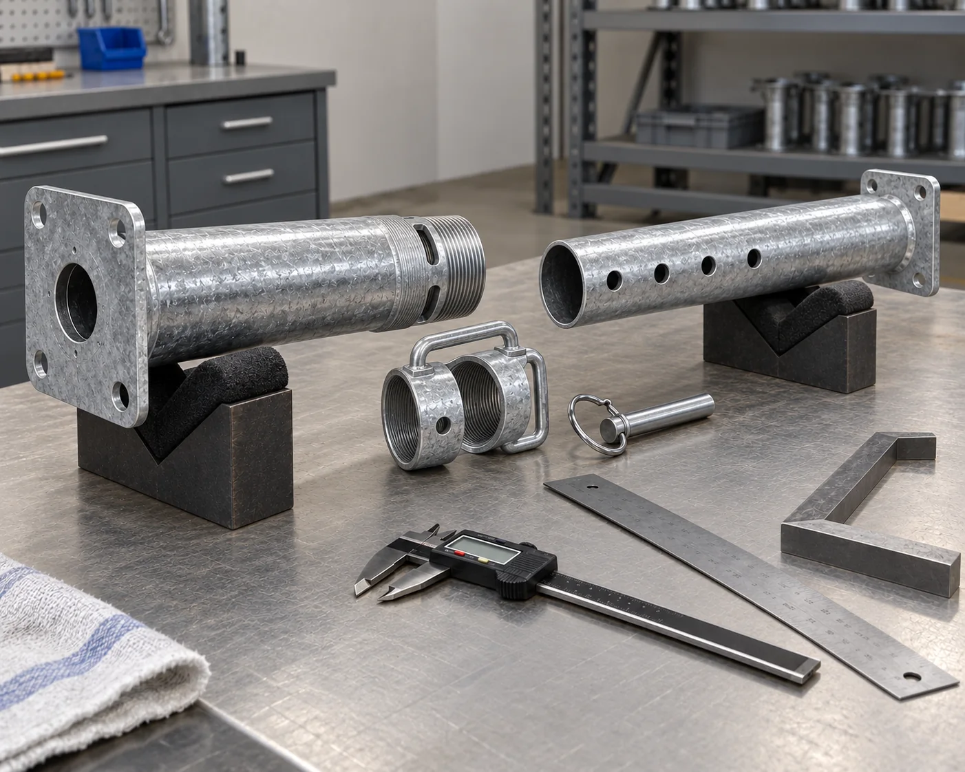
Tube geometry and adjustment function
Checks cover tube diameter, wall, length and pin-hole positions, followed by sliding movement, pin retention and nut travel on the assembled prop.
Welded ends and material identity
End checks cover plate geometry, alignment and specified weld inspection. Part and lot marks connect the completed assembly to its material and finish records.
Load evidence for the ordered working configuration
This range has no published model-by-extension load chart. A load-rated selection must use a record identifying the complete prop, working extension, end conditions and test or calculation basis. The component dimensions shown above cannot establish that rating.
The installed shoring arrangement
OSHA 1926.703 requires shoring to support the anticipated loads and addresses bearing contacts and site inspection. The installed layout and condition of the props must satisfy the project’s shoring design.
Records linked to the prop assembly
Model and revisionDimensions and adjustmentMaterial and finishConfiguration and load basis