Home » Products » Solar Mounting Systems » Solar Rail Splices

Solar Rail Splice Supplier

Profile-matched inserts, external connectors and complete joint kits

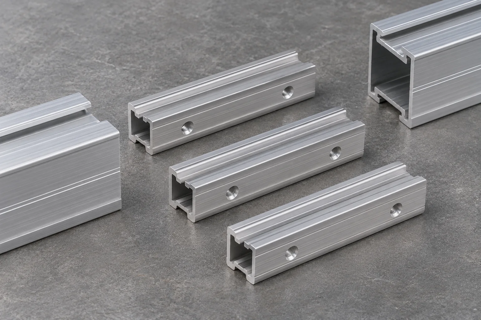
We supply solar rail connectors to the actual rail section and joint drawing. Internal inserts and external plates use different seating and fastening details; each kit identifies its connector and retaining hardware. The rail revision stays with the splice, so each joint is identified by its own pairing.

Connector forms
Internal inserts or external plates
Mating identity
Exact rail profile and revision
Order unit
Joint kits or bare connectors
Joint function
Defined by the mounting system

The rail splice and its mating section

Internal insertConnector seated within the selected rail cavity
External connectorPlate or shaped connector fixed to the specified outer rail faces
EngagementInsertion length or overlap defined by the joint drawing
Retaining partsSpecified bolts or screws, nuts and washers counted per joint
Rail endsCut condition, end spacing and permitted mismatch
Joint locationPosition relative to supports, cantilevers and movement breaks
Material and finishConnector and fastener materials identified separately

Rail segment and ordinary splice counts

A straight uninterrupted rail run made from S separate segments has S − 1 end-to-end joints. A pair of parallel runs doubles that joint count when their segment schedules are identical.

Segments in each rail run (pieces)Splice joints in one run (sets)Splice joints in two matching runs (sets)
100
212
324
436
548
6510

No matching specification. Clear the search to see every row.

Scroll sideways to see every column.

Count basis: ordinary joined segments within each continuous run. Expansion breaks and separately supported ends use their own specified assemblies, counted on separate lines. Fastener quantities follow the hardware schedule for each actual joint.

Structural joints, movement breaks and bonding

A fixed splice transfers the specified actions

The connector, engagement and fastening group form one joint. A connector designed for a particular rail is evaluated with that section and its support arrangement.

Movement uses a different detail

An expansion connection permits movement in a defined direction. An accepted movement joint is supplied as its own assembly.

Bonding follows the electrical arrangement

A structural connector can have a separate bonding role in the evaluated mounting system. Where bonding is required, the applicable components and assembly conditions identify that path; clean-looking metal contact is insufficient evidence.

Insertion, retaining screws and aligned rail ends

Internal seating and insertion marks

The connector enters to the engagement stated on its detail. Any center stop or insertion mark has a defined position, making the intended share within each rail end visible before the joint is hidden.

External plate bearing faces

An external connector bears on the specified rail faces. Hole centers, slot direction and fastening access belong to that plate detail, not to a generic flat strap with similar overall length.

A clear path for retaining hardware

Screw tips and bolt ends must clear the required rail channel or cavity. The selected fastener length avoids creating an obstruction for sliding clamp nuts, cables or other parts that occupy that space.

Alignment at the butt

The connected rail ends retain their intended line and support plane. A misaligned top slot can obstruct hardware even when the outside rail faces appear close; burrs and damaged lips are resolved before assembly.

Splice kits for rail lots and identified repairs

New rail cutting schedules

The cutting plan establishes where joined segments occur. Our component list separates ordinary splice kits, movement connections and any end hardware so each rail end is quoted as the joint it actually is.

Replacing a missing connector

The retained rail cross-section and its original joint detail identify the replacement. Insert fit and screw position come from that cross-section and joint detail.

Connector fit and joint hardware checks

External rail connector and rail section beside a caliper

Finished profile and engagement

The insert or plate is checked against the intended rail. Finish buildup, damaged ribs or an incorrect corner radius can affect seating; full engagement is checked from the actual joint datum.

Fixing holes and kit contents

Hole or slot locations and the retaining hardware are matched to the connector revision. Body dimensions and screw count answer different receiving questions and are recorded separately.

Rail joint trial fit

A representative fit checks rail-end alignment, insertion and access to the retaining parts. Where a structural or bonding test is required, its method and acceptance record are separate from that dimensional trial.

Rail joint supply records

Rail and connector identityEngagement detailFastener scheduleRequired assembly records

Bare connectors and complete splice kits

A clear per-joint price

Our quotation states whether the price covers a bare connector or a complete fastening kit. Internal inserts, external plates and movement parts remain separate lines, with quantities and drawing references attached to each.

Protected mating edges

Small connectors are packed clear of loose rail ends. Divided groups protect seating ribs, holes and finished contact faces; fasteners are bagged against the joint they serve.

Kits allocated to the rail schedule

Packing groups can follow the rail profile and array area. Extra connectors and spare screw sets retain separate counts so receiving teams can reconcile the installed takeoff without consuming the spare allowance.

Solar rail splice purchasing questions

Can a splice repair a cracked or badly bent rail?

An ordinary rail splice is a joint between prepared rail ends, not an automatic repair for a damaged member. The responsible system or project review must identify any permitted repair or replacement before a connector is selected.

Can an expansion gap use the same fixed splice with fewer screws?

No substitution is assumed. The movement detail controls the connector, gap, restraint and any bonding provision. Removing hardware from a fixed joint changes its assembly rather than qualifying it as an expansion joint.

Does one splice kit include the rail lengths?

The kit contains the identified connector and listed fastening pieces. Rail lengths are separate supply lines unless the offer expressly includes an assembled rail package.

Can we use an insert from a different brand if it slides in?

Sliding fit does not establish joint resistance, retention or bonding. The replacement needs the rail geometry and required system records, with its proposed connector and fastener arrangement reviewed as that combination.

Should a splice always sit directly over a roof attachment?

The selected rail system and project layout determine permitted locations. A joint positioned over a support can have different conditions from a joint between supports; neither location is assumed valid without that detail.

Can a long rail be transported in two parts and joined later?

Yes, where the rail plan accepts the resulting joint and its location. The revised cut schedule and connector scope must be identified before shorter shipping pieces replace a released full length.

Quote the rail joints as complete named kits

Send the rail section and splice drawing with the joint counts, material and finish. Include required movement or bonding functions so our offer separates each connector form and its fastening pieces.

Metdax
Get a quote
Search Metdax

Language

Get a factory quote

Send your specifications or attach a material list.

Solar Rail Splices

Your information is used to respond to this inquiry. Privacy policy

sales@metdax.com

+86 177 7599 6440