
Ground Screws
Screw foundations defined by shaft, tip, thread, and head geometry for the specified structure and ground conditions.
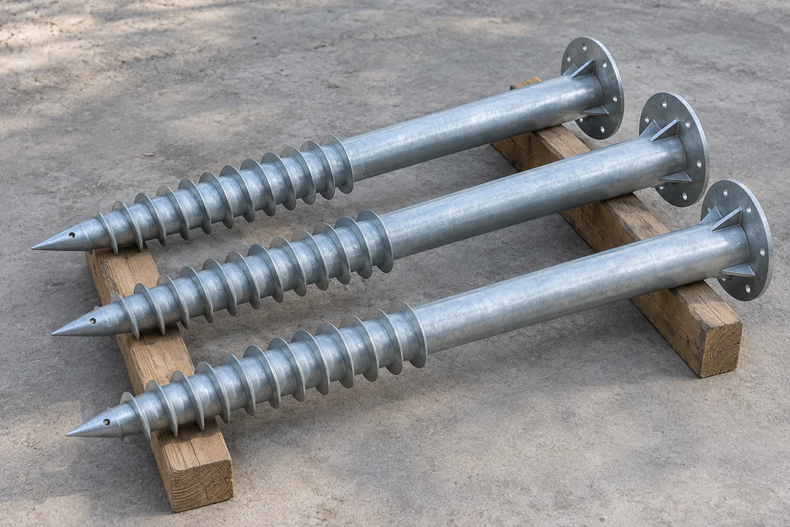
Screw foundations defined by shaft, tip, thread, and head geometry for the specified structure and ground conditions.
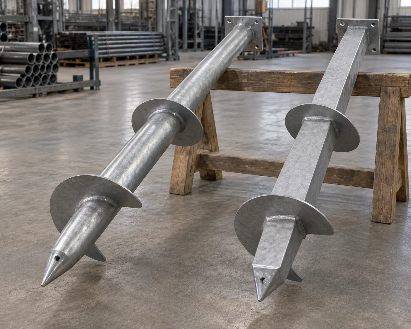
Lead sections with discrete helix plates and a defined shaft, selected with installation, structural, and geotechnical criteria.
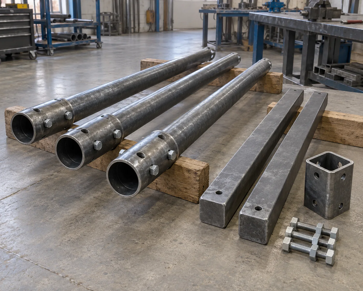
Extension shafts and couplings matched to the lead section, connection dimensions, torque rating, and installation tooling.

Pile caps, plates, and brackets that connect the shaft to a post, beam, or supported frame through an agreed load path.
No products match this search. Clear the filters to see the full range.
Ground screws combine the steel shaft, helical or threaded geometry and the top connection required by the supported structure. Compare the actual product drawing rather than the product name alone.
A pile lead defines the shaft and helix arrangement that enters the ground. Load direction and the site design identify the required assembly.
Extension shafts and joints continue the selected lead system. Mating geometry, bolt details and engagement must belong to that same assembly.
Head plates, caps and brackets connect the installed shaft to the support. Hole patterns, elevations and the supported member determine the connection.
| Component | Catalog dimension (in.) | Metric conversion (approx. mm) | Connection or selection detail |
|---|---|---|---|
| Round pipe shaft | 2-7/8 OD × 0.217 wall | 73.03 OD × 5.51 wall | Match the extension shaft and drive tooling |
| Helix plate | 3/8 thickness | 9.53 thickness | State blade diameter, count, pitch and spacing |
| Helix plate | 1/2 thickness | 12.70 thickness | Keep the selected plate thickness with the lead drawing |
| Coupling bolt | 5 length × 0.75 diameter | 127 length × 19.05 diameter | Match the sleeve, hole pattern and specified fastener |
Scroll sideways to see all table columns.
Each component mark identifies shaft section, grade, wall or bar size and cut length. Straightness and end preparation follow the selected coupling and drive connection.
The approved lead drawing defines thread or helix dimensions, orientation and attachment. Those features keep different lead configurations identifiable through fabrication and packing.
The system drawing defines mating dimensions, hole alignment, sleeve engagement and fasteners. Where connection tolerances are critical, the order can include a representative fit check against those specific parts.
Head plates and brackets follow the agreed connection pattern and finish schedule. Specified weld checks, galvanizing details and permitted repair areas stay attached to those fabricated items.
Leads, extension lengths, heads and hardware have separate marks and counts on the pile-schedule packing list. Protection covers helix edges, threads and finished mating surfaces.
Define foundation releases around the site investigation, accepted design and installation conditions.
Review plate grade and cutting requirements for drawing-defined helix plates, pile heads, and brackets.
Compare steel tube and galvanizing specifications while keeping ground-exposure durability requirements separate.
Separate the planned lead sections and heads from optional extension lengths and coupling hardware. Give the preliminary depth assumptions and requested delivery sequence. This allows the quotation to distinguish committed quantities from additions without implying that an estimated depth is the final installation criterion.
Removal does not establish suitability for reuse. The new project needs a review of the component's condition, dimensional changes, coating damage, connection wear, and service history, as well as different loads and soil. Reuse should follow an explicit inspection and engineering acceptance route.
Yes, submit the required component scope for review with the mating dimensions, system identification, material requirements, and quantities. A part that fits physically still needs the required connection and torque capacity. Identify any evaluation or warranty restrictions associated with the original system.
Send your screw-foundation component list or available drawings with quantities and destination. Identify the mating system and any preliminary site or design inputs. We will separate the leads, extensions, couplings and heads in the quote.