Home » Products » Construction & Infrastructure Products » Scaffold U-Head Jacks

Scaffold U-Head Jack Manufacturer

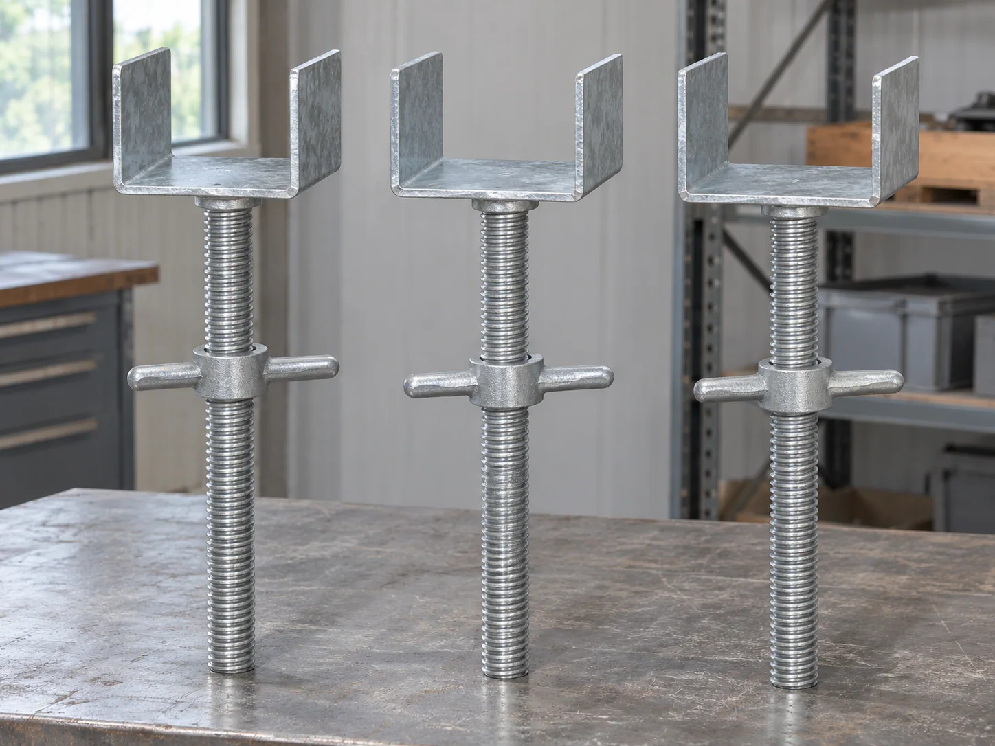
Adjustable fork-head assemblies with solid or hollow screw stems

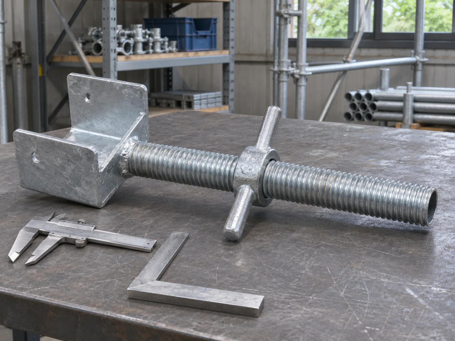
Our U-head jacks combine an open beam-support head, threaded stem and matched adjustment nut. The catalog lists solid and hollow models with their own head-plate dimensions and complete-unit weights. We supply these independent top-support assemblies by selected model, with the beam seat and receiving-standard interface retained on the drawing.
Head form
Open U-shaped beam seat
Stem choices
Solid or hollow
Adjustment
Matched handled nut
Order format
Complete U-head units

U-head assemblies and their two bearing interfaces

Upper seatHead plate and two side cheeks around the supported beam
Head dimensionsPlate envelope, cheek height, thickness and finished clear opening
StemSelected solid screw or threaded hollow tube
Adjustment nutMating thread and receiving-standard bearing face
Lower interfaceStem insertion, usable adjustment and standard bore
FinishPainted, electro-galvanized or hot-dip galvanized route

Solid and hollow U-head jack model references

Selected complete units from our factory screw-jack catalog. The catalog head-plate dimensions are retained with their corresponding stems and listed masses.

Stem formStem dimensions (mm)Catalog head-plate dimensions (mm)Listed unit mass (kg)
Solid30 × 400150 × 150 × 50 × 43.35
Solid30 × 600150 × 120 × 50 × 44.08
Solid34 × 400105 × 100 × 50 × 43.44
Solid34 × 600150 × 120 × 50 × 45.01
Hollow38 × 4 × 600150 × 150 × 50 × 53.99
Hollow38 × 4 × 660170 × 150 × 80 × 65.04
Hollow48 × 4 × 600150 × 150 × 50 × 85.23
Hollow48 × 4 × 900200 × 200 × 50 × 88.68

No matching specification. Clear the search to see every row.

Scroll sideways to see every column.

Factory catalog complete U-head jack references. Solid stems use diameter × length; hollow stems use OD × wall × length. The selected drawing establishes the finished clear seat, plate orientation, thread/nut fit and applicable adjustment/loading requirements.

Beam seat, side cheeks and spindle selection

The beam bears on the selected seat

The support detail identifies the beam or member stack and its bearing footprint on the head. The plate and cheek arrangement retain the beam orientation and required clearances.

The threaded stem matches the tower

Stem diameter, bore insertion and the nut bearing surface are selected for the receiving standard. Solid and hollow units retain their own complete component specification.

Adjustment at the stated working position

The accepted support detail gives the permitted exposed setting and minimum engagement. Those dimensions establish the complete head’s working position relative to the supporting standard.

Adjustable heads under EN 12811-1

A head with a means of limited vertical adjustment is assessed under EN 12811-1, the performance standard for access and working scaffolds; EN 74-3 covers plain base plates and loose spigots. Falsework erected to EN 12812 carries its own requirements. The adopted specification sets the duty.

Finished U opening and nut-to-standard bearing

Clear gap between the cheeks

The drawing locates the finished inside faces of both cheeks and the beam’s bearing surface. Those datums establish clearance for the supported member and its required placement.

Head orientation on the stem

The stem axis and U-head orientation are related on the complete assembly drawing. The selected attachment and plate planes keep the bearing seat in its intended position.

Thread travel in the finished condition

The handled nut and stem retain their matched thread profile and selected finish. Movement and engagement checks use the completed parts, including required thread preparation or lubrication.

Top-support component lots for formwork and scaffold towers

Independent U-head replenishment

A retained U-head drawing, beam-seat requirement and receiving-standard reference identify the replacement assembly. The model keeps all three interfaces together under one part reference.

Heads grouped with a shoring takeoff

The support schedule lists top-head positions and complete-unit quantities. Different head plates or stem models remain separate entries beside the tower and beam components.

U-head seat and finished spindle checks

U-head seat and stem checks

Head envelope and clear seat

The catalog head-plate dimensions, cheek planes and finished internal opening are checked against the selected head drawing. The bearing seat and stem axis share their specified datums.

Nut, thread and receiving fit

The finished nut moves over its required range with the specified engagement. The receiving-standard detail establishes the corresponding bore and bearing contact.

Head attachment and model records

Required attachment and finish checks stay linked to the assembly model. The record identifies the supplied stem, head and complete-piece quantity.

U-head component records

Complete-head assembly drawingHead plate and clear-seat dimensionsStem/nut/standard interfaceRequired attachment/finish checksComplete-unit count

Complete U-head pricing and fork-protected packing

A complete assembly on each price line

Our offer identifies the selected head plate, stem, nut, finish and number of complete U-head units. Separately requested components retain their own quantities.

Fork cheeks and screw stems protected

Packing supports the assemblies while providing clearance for projecting cheeks and threaded stems. Nut and model identities remain visible within the grouped parts.

Receiving by head and stem combination

Each different head/stem configuration has its own packing group. The list retains the complete model reference and the agreed shipment basis.

Scaffold U-head jack purchasing questions

Can the catalog head width be used as the clear beam opening?

The selected drawing gives the clear opening between the finished cheek faces. That dimension is checked with the supported beam or member stack and its required placement clearance.

Can one U-head support two adjacent beams?

The accepted support design identifies the intended beam arrangement and bearing footprint. The selected head detail then retains its clear seat, cheek configuration and loading requirements for that arrangement.

Is a telescopic prop’s U-head the same item?

A telescopic prop head follows its prop attachment and assembled-height detail. An independent screw U-head follows its own stem, nut and receiving-standard interface; the order identifies which complete component is required.

What datum defines the installed support height?

The support detail identifies the beam-bearing plane relative to the receiving standard and the permitted adjustment setting. The head geometry, inserted stem and nut position all enter that assembled height.

Which beam dimensions identify a U-head for an I-section?

The lower-flange width and required seat length identify the beam’s contact footprint. Its installed orientation, bearing location and access between the side cheeks remain on the support detail, alongside the complete I-section reference.

How is a through-tie opening specified in a U-head?

A through-tie arrangement is detailed with a continuous opening through the head seat and stem. The component drawing identifies the opening diameter, position and tie-bearing arrangement together with the head and spindle sections required for that support.

Related guides and order tools

Get a scaffold U-head offer

Send the head/stem model or drawing, clear beam-seat requirement, receiving-standard detail, unit quantities, finish and destination. We quote the complete U-head configuration and any separately listed components.

Metdax
Get a quote
Search Metdax

Language

Get a factory quote

Send your specifications or attach a material list.

Scaffold U-Head Jacks

Your information is used to respond to this inquiry. Privacy policy

sales@metdax.com

+86 177 7599 6440