Home » Products » Steel Structures » Power & Substation Structures

Substation Steel Structure Manufacturer

Galvanized gantries and equipment supports made to utility drawings

Substation columns, crossmembers, bracing and equipment frames are fabricated around the specified equipment and connection layout. Base plates, mounting holes and attached supports follow the approved drawings, with steel and hardware grouped by structure.

Steel package
Gantries & support frames
Mounting details
Drawing-defined plates
Finish options
Galvanized or painted
Order basis
Structure schedule & BOM

Steelwork included in the substation package

Structures and attachment components are itemized from the approved steel schedule
Package itemSteelwork suppliedInterface controlling fabrication
Gantry framesColumns, crossmembers and brace connectionsFrame arrangement, member lengths and field joints
Bus support steelPosts, crossmembers and attachment platesInsulator mounting positions and support elevations
Equipment support framesFabricated stands and mounting steelEquipment base pattern, orientation and attachment detail
Base connectionsBase plates and welded stiffenersAnchor-hole layout and foundation datum
Bracing and tiesAngles, tubular braces and connection platesBrace positions, member ends and joint details
Connection hardwareBolts, nuts and washers listed in the packageGrade, diameter, length, finish and assembly count

Scroll sideways to see every column.

Electrical apparatus, insulators, grounding conductors and foundation work remain separate from this steelwork package. Anchor rods and equipment mounting bolts have their own supply lines, so their quantities are visible alongside the structural connection hardware.

Equipment elevations, mounting holes and structural clearances

Top plates that match the equipment

An equipment support has two sets of interfaces: its foundation base and the face carrying the equipment. The OEM mounting pattern sets the top-plate hole centers, slot direction and available bolt access. Support height is measured to the defined mounting surface so the equipment arrives at its required elevation.

Gantry geometry and installed equipment

Crossmember position, brace placement and the station grid establish the steel arrangement. Electrical clearance envelopes and equipment operating space come from the approved station design. We carry those interfaces into the fabricated steel without treating a voltage class as a universal support size.

Find an equipment, base or connection dimension.

Drawing dimensions identify the ordered assembly; there is no fixed universal substation model
InterfaceDimension / unitFabrication detail
Support elevationMounting-face height; in. or mmDatum and installed equipment orientation
Equipment attachmentHole centers and plate size; in. or mmOEM base drawing and required bolt access
Structure gridColumn centers and crossmember span; ft or mmStructure ID and station arrangement
Base platePlate thickness and anchor grid; in. or mmFoundation template and column centerline
Field jointHole diameter, pitch and edge distance; in. or mmConnection detail and specified bolt assembly

No matching requirement. Clear the search to restore the table.

Scroll sideways to see every column.

The project engineer establishes structural loads, deflection criteria and electrical clearances. Fabrication follows the released steel and equipment interface drawings, with any changed hole pattern or mounting elevation recorded in the approved revision.

Member grades and mounting-plate materials

Columns, crossmembers, braces and attached plates keep their individual material specifications in the bill of materials. A rolled shape, structural tube and fabricated plate use different product standards. The exact section designation stays with each member; a metric H section does not replace a US W section solely because their depths appear similar.

SSAB US plate reference values at the listed thicknesses
Plate gradeReference thickness (in.)Minimum yield (ksi)Tensile strength (ksi)
ASTM A360.100–6.003658–80
ASTM A572 Grade 500.100–4.005065 minimum

Scroll sideways to see every column.

Plate grade and thickness identify the base material. Structure capacity comes from the approved member, connection and foundation design; it is not the plate’s yield strength expressed as a support rating.

Galvanizing requirements by steel component

Hot-dip galvanizing is applied after the approved cutting, drilling and welding work. The zinc acceptance basis follows the material category and measured steel thickness. Rolled shapes, plate and tubular members in the same assembly can therefore carry different minimum average coating requirements.

ASTM A123 minimum average coating reference at selected measured steel thicknesses
Material categoryMeasured steel thickness (mm)Minimum average zinc (µm)
Structural shapes8100
Plate875
Pipe and tubing875
Structural shapes20100
Plate20100
Pipe and tubing2075

Scroll sideways to see every column.

These values set the coating reference for the listed category and thickness. The inspection record identifies the actual components, measurement areas and acceptance basis. Fabricated columns formed from plate retain the plate category; their finished shape alone does not make them manufactured pipe or tubing.

Hole preparation, venting and field connections

Finished holes before galvanizing

Connection and equipment holes are prepared to the released detail before the galvanized finish is applied. Hole pattern, member orientation and access for a nut or wrench belong to the same joint. This gives the installer a defined connection instead of a plate that must be redrilled to suit the equipment.

Vents and drains in hollow assemblies

Closed sections and attached plates need a venting and drainage arrangement that allows cleaning liquids and molten zinc to move through the assembly. Round, square and rectangular hollow members use details suited to their geometry. The approved openings are included in fabrication before the steel reaches the galvanizing stage.

Structural and equipment hardware

The connection drawing sets the required bolt access, grip length and washer arrangement. Hole clearance and finished contact faces are checked with the specified hardware, including the coating allowed at that joint.

Steel packages for new bays and equipment changes

New substation bays

A new bay combines gantry and equipment support sets at their station-grid positions. Structure IDs tie each steel assembly to its equipment interface and foundation reference. The package schedule keeps repeated support types together while identifying any distinct mounting detail.

Equipment replacement

Replacement equipment can change the mounting footprint or the elevation at its terminals. The revised support detail establishes which steel members remain and which plates or frames are replaced. Matching only the previous equipment type can miss those interface changes.

Grid connection projects

Renewable-energy and industrial grid connections require the same coordination between utility steel, equipment and civil works. Our supply covers the fabricated structural package; the project’s electrical and foundation designs establish the final interfaces and acceptance requirements.

Support fit, coating checks and release records

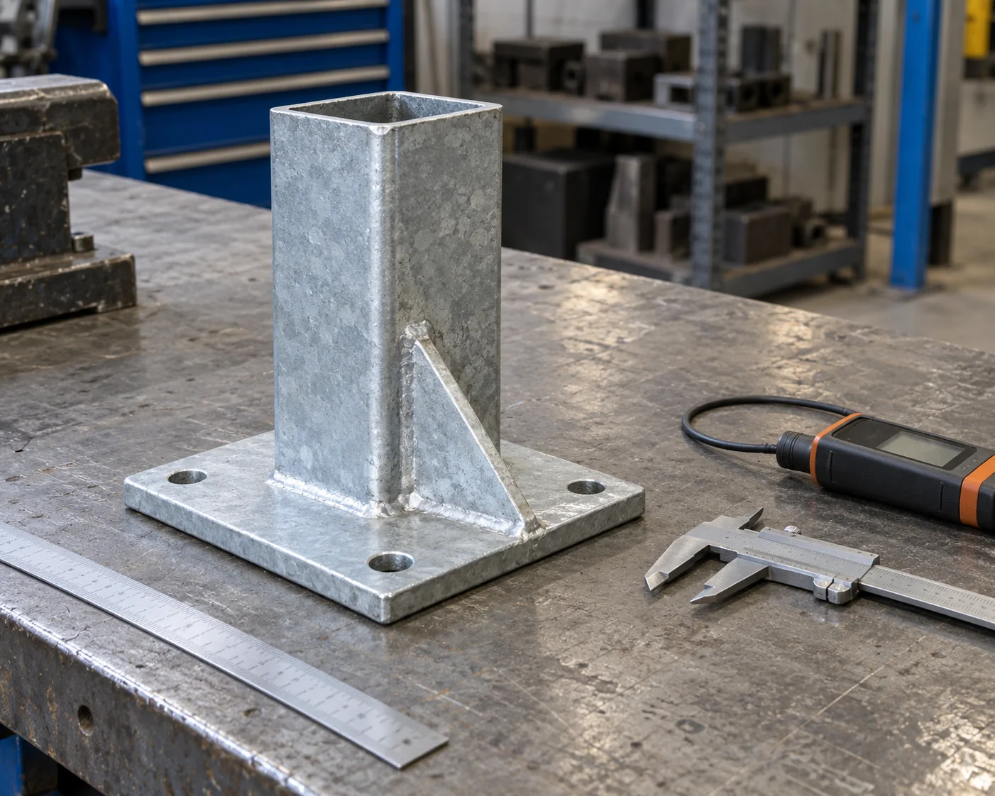
Galvanized hollow support stub and drilled base plate beside dimensional and coating tools

Mounting and base dimensions

Support height, plate position and hole centers are checked from the drawing datums. The equipment-mounting face and the foundation base are recorded separately. This checks the interfaces that have to match at installation, in addition to the member’s overall length.

Weld requirements

Weld size, joint type and examination scope follow the fabrication specification. AWS D1.1 provides the structural-steel welding framework when the project requires it. The order’s inspection plan identifies the applicable procedures, acceptance criteria and required records.

Galvanized coating and usable joints

Coating checks follow the component category and thickness specified for the order. Connection areas are also checked for zinc buildup, blocked holes and handling damage that could interfere with assembly. Approved repair work retains its own location and record.

Structure marks and document identity

Structure and shipping-piece marks link the supplied steel to its material identity, drawing revision and inspection records. The same marks appear on the packing schedule.

Records for the supplied substation steel

Drawing revisionMaterial identityDimensional checksFinish and packing

Substation steel pricing and dispatch groups

A quotation by structure and component

Substation prices itemize the structure sets, fabricated members, plates and included hardware. Finish, inspection documents, packing and freight are listed with the production and delivery terms.

Hardware matched to the steel sets

Hardware is boxed by connection group and structure mark, with bolt, nut and washer counts listed by size and grade. Any spare erection sets have their own counted line, so the site team can reconcile the cartons against the assembly schedule.

Protected galvanized surfaces

Columns and crossmembers travel on supported stacks, with contact protection at straps and attached plates. Spacers allow water to drain and air to move between zinc-coated pieces. Packing groups follow the bay or structure sequence, with piece counts matched to the dispatch list.

Substation steel purchasing questions

Can the quote follow an existing utility structure standard?

Yes. The utility standard drawing, its current revision and the required structure quantities form the quotation basis. Project-specific equipment interfaces and any approved changes remain attached to that structure schedule.

Can I order replacement mounting plates without new support frames?

A plate-only quotation identifies the support mark, plate drawing and quantity. Hole pattern, thickness and attachment detail follow the approved replacement drawing. Existing frame members remain outside that order unless separately listed.

Can you quote from a preliminary station layout?

A preliminary layout and equipment support list can start a budget quote. The offer states its drawing basis and included steelwork. Fabrication starts from the approved member, connection and mounting details.

Who supplies US-stamped engineering and utility vendor approval?

The project’s licensed engineer provides the required US design stamps, and the utility’s procurement process establishes vendor qualification. Our supply agreement identifies the fabricated steel and the documentation included in the package. The approved engineering and utility requirements form the order’s acceptance basis.

Are hollow support frames drilled before galvanizing?

Fabricated holes, vents and drains follow the approved fabrication and galvanizing details. Connection areas are checked for blocked holes and zinc buildup so the finished parts remain usable for assembly.

Get a quote for your substation steelwork

Share the structure schedule or station layout with quantities and the delivery destination. Equipment mounting drawings and base details identify the interfaces. We quote the fabricated steel, listed hardware, finish, inspection records and shipment terms against the stated drawing revision.

METDAX
Get a quote
Search METDAX

Language

Get a factory quote

Send your specifications or attach a material list.

Power & Substation Structures

Your information is used to respond to this inquiry. Privacy policy

ruofan1901@gmail.com