Home » Products » Solar Mounting Systems » Solar Mounting Rails

Solar Mounting Rail Supplier

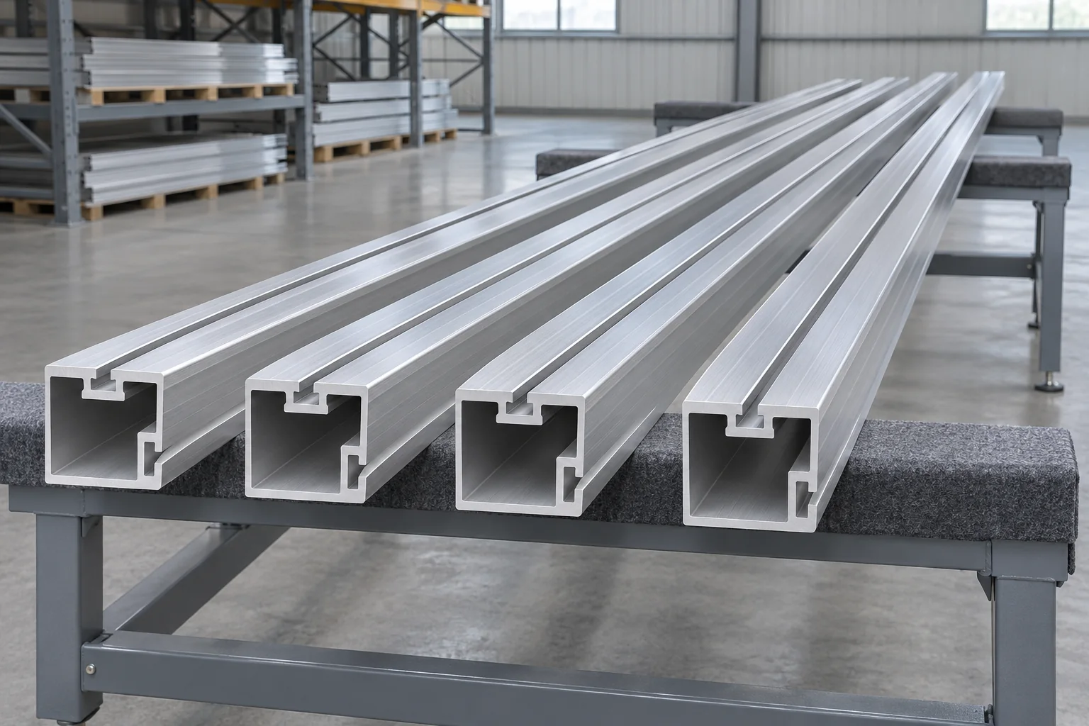
Profile-matched rails, cut lengths and prepared fastening channels

Solar rails are ordered by their cross-section and mating parts, as well as their finished length. We supply drawing-based rails for module clamps, mounting feet and the specified splice system. The quotation identifies the material, finish and cut schedule without substituting a visually similar channel.
Rail definition
Controlled cross-section drawing
Prepared lengths
Full or specified cut pieces
Mating hardware
Clamp, foot and splice references
Purchase unit
Lengths and piece counts

Rail profile and cut-length supply

Section identityRail drawing and revision, with height, width and wall geometry
Upper connectionModule-clamp channel and captive nut or bolt-head seat
Support connectionSide or lower fastening detail for the selected mounting foot
Joint interfaceSplice cavity or external connecting face, fixing pattern and engagement
Material routeSpecified aluminum alloy or steel section for the released rail
FinishMaterial-specific surface treatment and required contact-face condition
End preparationFinished cut length, square cut, deburring and any specified holes
Supply quantityPiece count for each profile, cut length and finish

Finished-length notation for rail schedules

Keep the original unit with the cut schedule. The lengths below show the exact metric equivalent of common foot-based callouts. Stock lengths are confirmed on the offer.

Ordered length (ft)Ordered length (in.)Equivalent finished length (mm)
6721828.8
8962438.4
101203048.0
121443657.6
141684267.2
202406096.0

No matching specification. Clear the search to see every row.

Scroll sideways to see every column.

Length conversion uses 1 in. = 25.4 mm. Each quoted rail line retains its original dimension and permitted cut variation. Available parent lengths, cutting allowance and packing limits are resolved for the selected profile; installed run length also includes the specified joints or breaks.

Rail section properties and the support layout

Span belongs to the selected section

Wall layout, material and orientation affect the rail’s stiffness and resistance. The actual section and the project design establish the allowable span and cantilever.

Module support locations

Rail positions must agree with the permitted support or clamp zones of the exact module. A rail that meets its own dimensional checks can still be in the wrong place beneath that frame.

System identity at joints

Where evaluated mounting or bonding parts are required, their identity stays with the rail, clamps, splices and fasteners. Each rail system carries its own records.

Channels, cut ends and splice locations

Top slot and nut insertion

The channel lip carries the captive nut or bolt head. Slot opening, bearing width and insertion route must match the fastener; cut ends remain accessible where the hardware has to slide in from the end.

Foot connection and rail rotation

The mounting foot fixes a particular rail face. Turning the extrusion onto a different face changes the section orientation and fastening relationship, even if a bolt can be made to enter the channel.

Cut lengths and edge condition

Finished pieces retain their cut datum and requested length variation. Deburring clears the rail lips and cavity so a connector or sliding nut runs past the cut edge.

Joints in the rail plan

The selected system controls splice positions relative to supports and cantilevers. Transport breaks are placed at accepted splice locations, and movement breaks use their own detail.

Rail supply for OEM arrays and replacement sections

Repeated module tables

A table schedule can use several cut lengths from one cross-section. Piece marks distinguish end rails and intermediate pieces, keeping the installed arrangement visible even when the profiles look alike.

A replacement rail in a retained system

The new section must match the clamp, foot and splice interfaces that remain. Measurements of only the damaged piece’s outside width are insufficient where the internal slot or joint cavity has changed.

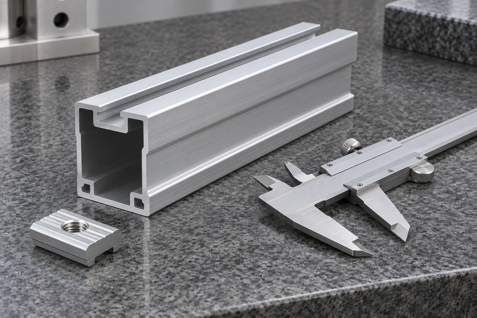
Rail dimensions and mating hardware checks

Rail profile beside a caliper and matching channel nut

Profile geometry

The check includes the top opening, slot lips, support channel and splice cavity. Those features identify the rail more reliably than a matching height and width.

Length, straightness and twist

Finished length and the required straightness or twist limit use the agreed measurement stage and method. Supporting the rail during inspection avoids confusing its deflection under handling with a permanent shape deviation.

Prepared ends and fitted parts

End checks look for burrs, crushed lips or blocked cavities. A representative nut, foot or splice checks the intended mechanical interface; any required structural or bonding evidence remains separate.

Rail supply records

Profile and revisionMaterial and finishCut scheduleRequired dimensional results

Rail lengths priced and packed by profile

Piece lengths and preparation

Our quotation states the profile and the number of pieces at each finished length. Cutting, specified hole work, splices, feet and fastening kits appear as named supply items, with the accepted material and finish.

Supported bundles

Rails are separated at finished contact faces and supported along the bundle. Straps and bearers keep thin lips and open channels away from point loads that could distort the mating profile.

Transport length and receiving

The longest packed piece and bundle size matter to container loading and unloading. Any proposed shorter shipping lengths are reviewed with the joint plan before they replace the released rail schedule.

Solar rail purchasing questions

Can a rail be chosen only from the module wattage?

No. Wattage does not identify the module frame or its permitted support locations. The rail selection also needs the actual module geometry, support layout, actions and mating components.

Does a 14 ft rail mean 4,200 mm?

Fourteen feet is exactly 4,267.2 mm. A 4,200 mm piece is a different finished length. The order retains the original dimension rather than rounding it into a shorter metric rail.

Can rail offcuts be joined wherever they fit?

The rail system and project detail establish permitted joints and splice positions. An offcut is usable only where its length and connection arrangement form part of that accepted plan; physical fit alone is not an approval.

Can modules be used to pull a bowed rail straight?

The module frame is not an alignment tool. The rail and supports must meet their required geometry before module retention; forcing the frame onto a distorted support can change contact and mounting stresses.

Are end caps included with every rail?

End caps are separate counted components unless the offer lists them with the rail. Their profile fit and any drainage or cable-clearance requirements belong to the selected rail detail.

Can rails be drilled or cut on site?

Only work permitted by the rail and project instructions is carried out. The accepted detail identifies the cut or hole position, deburring, finish repair and any effect on fastening or bonding; a convenient field modification is not assumed in a factory rail order.

Quote the rail section and cut schedule together

Share the profile drawing, material and finish, piece lengths and quantities, plus the clamp, foot and splice references. We will itemize the rails and preparation with the required packing length and destination.

Metdax
Get a quote
Search Metdax

Language

Get a factory quote

Send your specifications or attach a material list.

Solar Mounting Rails

Your information is used to respond to this inquiry. Privacy policy

sales@metdax.com

+86 177 7599 6440