Start with One Duty and One Equipment Layout
The Minimum Information to Compare
Bring the selected pump data sheet, valve schedule, pipe specification and current layout together. Use the same fluid, operating range, design pressure and temperature, connection references and drawing revisions. A quotation saying “standard flange” or “suitable motor” leaves an important part of the order undefined.

The checks below cover different failure mechanisms. A geometrical mismatch needs a different remedy from an unsuitable seal or a pump that cannot meet the required flow. Record the affected item and the correction needed; a single general statement that the package is compatible is too broad.
Swipe to view the complete table.
| Risk | Compare | A usable result |
|---|---|---|
| 1. Connection geometry | Both mating drawings and end standards | A joint with matching geometry and assembly requirements |
| 2. Pressure at temperature | Component ratings for the selected materials and duty | Every component suitable for the defined design conditions |
| 3. Wetted materials | Body, trim, lining, gasket and seal schedule against the fluid | A complete accepted material combination |
| 4. Installed space | Face-to-face dimensions and movement/access envelopes | A layout that fits and can be operated and serviced |
| 5. Hydraulic duty | Final system resistance and selected pump curve | Required operating range checked with the actual components |
| 6. Piping loads | Support layout, alignment and pump connection limits | A supported connection within the applicable limits |
| 7. Electrical controls | Supply, motor, actuator and control-system data | Matching power, command, feedback and required failure behavior |
1. The Nominal Size Matches, but the Joint Does Not
Compare the Two Mating Drawings
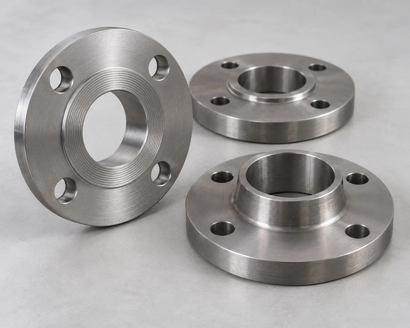
Compare the connection standard and the actual mating dimensions. For flanges, look at the bolt circle, hole count and size, face type, bore and any moving-part clearance. For other joints, use the thread, groove or weld-end preparation. The size name is a starting point, not a complete connection description.

Ask the two suppliers to identify the offered ends on their drawings. If they differ, select a matching offered end or obtain a designed transition. The transition also affects installed length, rating and sometimes hydraulic resistance. Do not release an improvised drilling or machining change as an ordinary site adjustment.
2. A Pressure Class Is Mistaken for a Complete Rating
Use the Actual Material and Design Conditions
Check the permitted pressure at the temperature for the actual component and material configuration. The pump casing, valve body and trim, flange joint and pipe each need to suit the duty. A catalog class label cannot replace that review, and different rating systems should not be treated as equivalent by their names.
Use the design conditions supplied by the responsible system designer, including relevant abnormal conditions. Where an offer omits the applicable temperature or material, request the corresponding rating information before selecting it. Choosing a higher class in one item does not increase the rating of the rest of the assembly.
3. The Metal Body Fits the Fluid, but the Seal Does Not
Include the Parts That Actually Touch the Fluid
A body-material description can hide different seat, gasket, lining and mechanical-seal choices. Compare the complete wetted-material schedule against the fluid composition, concentration, temperature and any cleaning medium included in the service. A metal designation by itself cannot establish the suitability of every internal part.
Request the offered material options by item, especially where a quotation allows an unspecified equivalent. If a seal or lining changes, have its suitability checked for the stated conditions. Keep the accepted configuration attached to the order so a later substitution does not silently reopen the question.
4. It Bolts In, but Cannot Be Operated or Removed
Check the Full Movement and Service Envelope
Place the actual valve face-to-face length, pump nozzle positions and operator envelope in the equipment layout. Include the movement of handwheels, levers or actuators and the access needed for the planned service procedure. A valve may fit between flanges while its operator conflicts with a wall or another item.
Where a butterfly disc moves into the adjoining bore, use the selected valve’s disc-travel and service-clearance requirements on the layout. Resolve a conflict through component orientation or a revised arrangement, then check the connection and service space again.
5. A Valve Substitution Changes the Pump Operating Point
Use the Final Components in the System Assessment
For a centrifugal pump, the operating point depends on the intersection of the pump curve and the system resistance curve. Selecting a valve with different loss characteristics can therefore change the resulting flow, even when its nominal size and connection fit. The importance depends on the actual system and valve operating position.
Give the system designer the final valve and fitting data, intended positions and pipe layout. Recheck the required flow range against the selected pump curve and the relevant suction and operating limits. A supplier’s duty point for the pump alone does not establish performance with every possible piping package.
6. Pipe Fit-Up Loads the Pump Connection
Separate Pipe Support from Pump Alignment
A flange can line up geometrically while the connected pipe places an unacceptable force on the pump. Review the pipe supports, anchors and fit-up against the selected equipment’s installation requirements. For example, the e-MPV manual requires independent piping support and warns against forcing pipe into position.
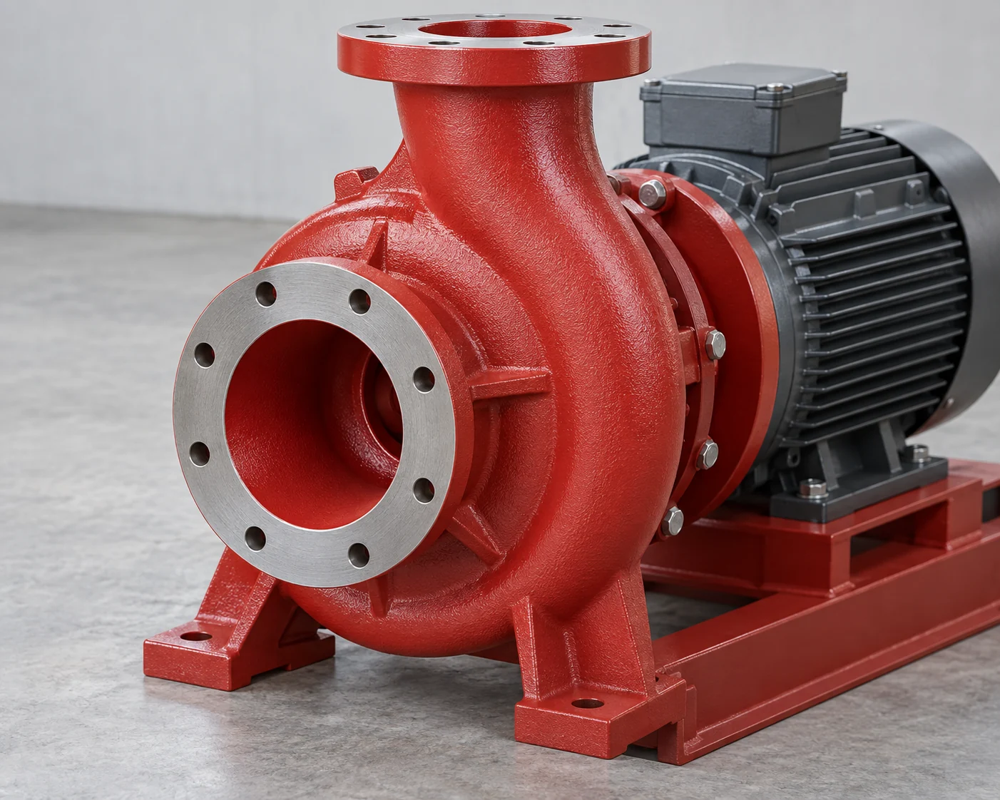
Have the proposed support arrangement and applicable nozzle-load limits checked for the project. Where alignment depends on pulling the pipe toward the nozzle with bolts, correct the fit-up rather than treating bolt tightening as a remedy. A support change can affect the pipe layout, so use the final arrangement in the connection review.
7. The Power Matches, but the Control Signals Do Not
Distinguish Supply, Commands and Feedback
Compare motor voltage, frequency and phase with the intended supply. For actuated valves, check power and control interfaces separately: command inputs, position feedback, open/closed indication and any required interlocks. An available feedback signal is not necessarily an accepted command input.
Check the exact actuator option and its wiring information against the control-system requirements. State the required responses to loss of command and loss of power separately; they are different events. A suitable supply voltage does not prove that the offered actuator provides the required signals or returns to a particular position on power loss.
One Order, Two Corrections Before Release
The Initial Hold
In this hypothetical order, a buyer has selected pipe, valves and a centrifugal pump from three suppliers. The project team has accepted the materials, pressure-temperature ratings, space and hydraulic assessment. A final interface review finds two remaining problems: the valve and mating pipe-flange drawings show different drilling patterns, and the actuator offer identifies a position-feedback output but leaves the required command input unconfirmed. No real supplier or customer result is represented.
Hold the affected valve configuration. Ask for a valve end matching the piping joint and a documented control option that accepts the required command. Replacing all three brands would not solve these two defined gaps more directly. Adding an adapter would create another joint and alter the installed length, so it is a separate design option rather than an assumed fix.
The Configuration That Can Be Released
Assume the revised valve drawing now matches the joint, the control option is confirmed and the project team accepts the resulting layout and hydraulic review. Release that identified configuration with the revised documents. If its face-to-face length, loss data, materials or control option changes again, reopen the corresponding checks. The completed result is a particular compatible package under stated assumptions, not blanket approval of the brands.
Frequently asked questions
Does buying one brand remove these checks?
No. One brand can offer different connection, material, rating and control options. The order still needs the selected configurations and a system assessment. One supplier may simplify communication, but its name does not define the interfaces.
Can an adapter solve every flange mismatch?
An engineered transition may be an option, but its rating, joints, length, support and flow effects must fit the project. Compare that complete option with selecting a component that already has the required end. Do not assume field redrilling is an equivalent solution.
What if a supplier changes a component after order placement?
Ask which accepted fields change: geometry, materials, rating, loss characteristics, mass/support or controls. Recheck those interfaces and connected consequences before accepting the substitution. A model described as equivalent still needs that comparison.
Does a pressure test prove the complete package is compatible?
It demonstrates only what the test covers. It does not by itself establish operating flow, chemical suitability for the intended service, maintenance access or control-system behavior. Retain those separate acceptance checks.
Should spare valves match the original brand?
Define the installed configuration that the spare must replace, including ends, face-to-face length, materials, rating, operation and controls. A different brand may be a candidate if those requirements are met and accepted; the same nominal size is insufficient.
Who should resolve conflicts between supplier data sheets?
Nominate the project party responsible for the affected system design. Suppliers provide their actual product data; the responsible designer decides whether the proposed combination meets the project requirements. Close the specific conflict in the accepted drawings or schedule before release.
Technical Basis and Source Scope
Xylem, e-MPV Vertical Multistage Pump Instruction Manual, P7000002 Rev 2, Sections 3.1–3.3, 3.7, 4.1.2, 4.2 and 4.5–4.7: material options, model-specific ratings, support, electrical supply and fit-up. Keystone Figure 56 Butterfly Valves Installation and Maintenance Instructions, VCIOM-00757-EN, 04/18, Sections 2.2–2.5: flange matching, disc clearance and operation space. The latter is a discontinued-model example of interface checks, not a product recommendation.
US Department of Energy, Operations & Maintenance Best Practices Guide, Release 3.0, Section 9.9.9, printed page 9.103: pump and system-curve intersection. Valmet/Valvcon, V-Series Option U instructions, IMO-I5500EN, 4/2022, Sections 1.2–1.3 and 3.1–3.2: actuator limits and distinct control/feedback interfaces. These sources explain the mechanisms; use the selected equipment’s current documents for an actual order.