Home » Products » Steel Structures » Bridge Cross-Frames

Bridge Cross-Frame Manufacturer

Transverse bracing assemblies matched to girder geometry and the released fit condition

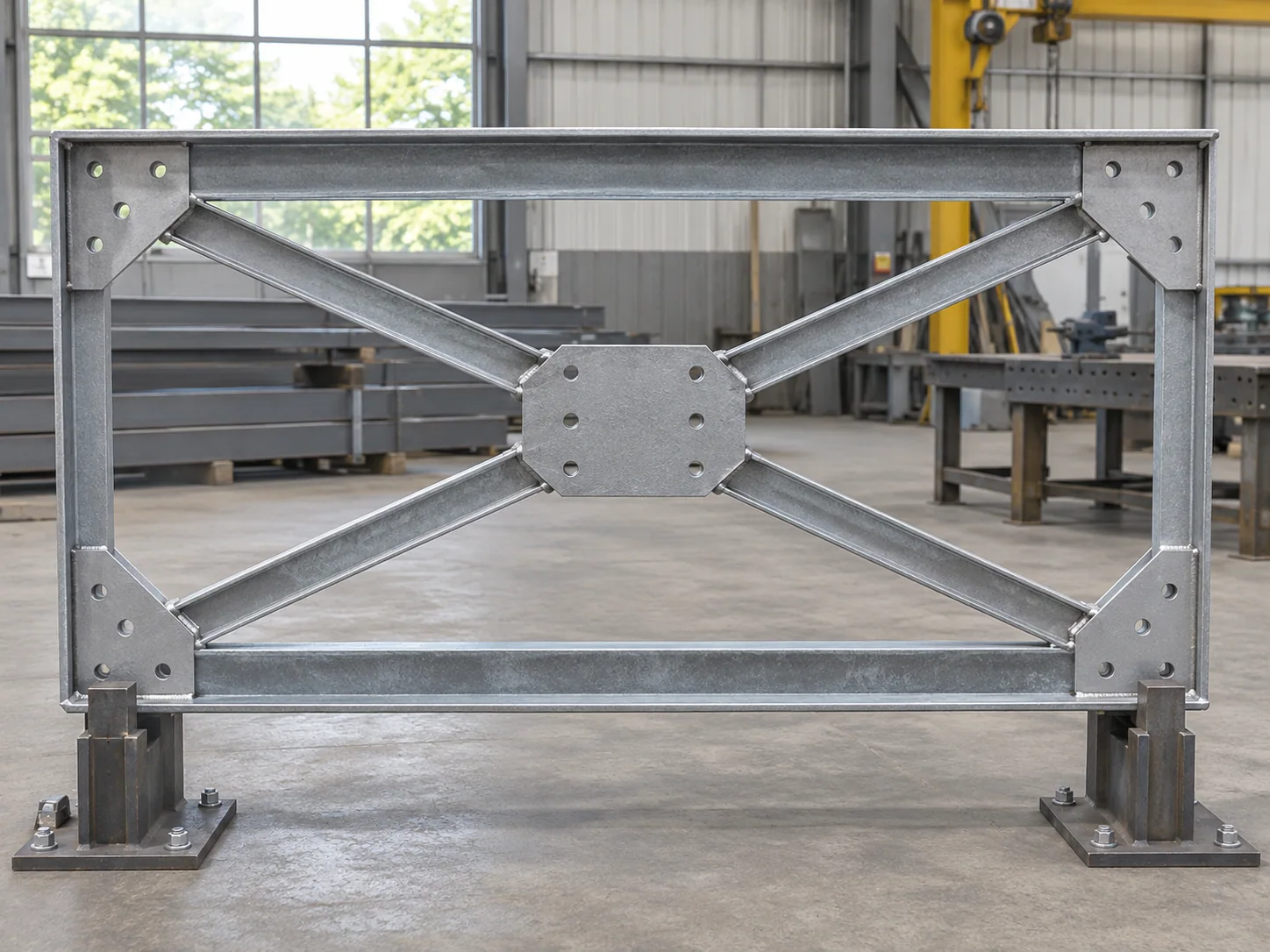
Bridge cross-frames are fabricated as marked transverse assemblies with their chords, diagonals and end connections kept together. We prepare each frame for its assigned girder bay, skew and connection orientation. Complete welded units and separately scheduled bolted pieces have their own fabrication and packing scope.

Order object
Marked transverse assemblies
Forms
Drawing-defined X, K or other frame
Interfaces
Girder connection plates
Delivery
Complete units or listed pieces

Cross-frame assemblies and end connections

Frame layoutChords and diagonal arrangement from the released frame detail
LocationGirder bay, station and frame mark
End planesConnection orientation and offset at each girder
Fit conditionSpecified girder geometry/load condition used for detailing and fit-up
Joint detailsGussets, end plates, holes and shop/field connections
FinishMember surfaces and joint contact areas specified separately
HardwareField connection bolts, nuts and washers itemized

Standard round-hole reference for bolted frame joints

Nominal structural-bolt diameter and standard round-hole diameter are separate dimensions. The actual project joint retains its specified hole type, bolt and connection design.

Nominal bolt diameter (in.)Standard round hole (in.)Hole diameter converted (mm)
1/29/1614.288
5/811/1617.463
3/413/1620.638
7/815/1623.813
11-1/828.575

No matching specification. Clear the search to see every row.

Scroll sideways to see every column.

RCSC 2020 Table 3.1 nominal standard round-hole reference. Inch-to-millimeter conversions use 25.4 mm/in and are rounded to 0.001 mm for identification. Manufacturing tolerance, hole type and erection allowance follow the accepted project connection detail.

Girder fit, frame function and joint identity

Fit condition stated before detailing

Cross-frame ends are coordinated with the girder geometry in the specified condition. Self-weight deflection, slope and twist can affect fit; the issued detailing basis establishes which geometry the fabricated frame is intended to match.

Frames and temporary restraints

Permanent cross-frames and temporary erection braces have separate roles and acceptance details. Each supply mark identifies the specified component and the restraint function assigned by the project design.

Bridge welding and bolted joints

The fabrication specification identifies required weld procedures, examinations and bolt installation requirements. An end plate or gusset keeps its actual material and joint-surface treatment in that schedule.

End orientation and complete-unit fabrication

Left and right ends are located independently

Skewed or sloping connections can give the two ends different planes and offsets. The frame drawing states its viewing direction and member axes, keeping each end tied to its intended girder connection.

Chords, diagonals and gussets share the same datums

Member end cuts and gusset positions follow the assembled frame geometry. Weld access and connection-hole clearances are checked in the complete arrangement.

Complete units reduce loose-piece ambiguity

Where the design permits, a complete shop-assembled frame has one orientation and assembly mark. A frame shipped in pieces retains the joint pieces, field hardware and assembly references needed to reconstruct that unit.

Fit-up method agreed for the interface

A required template or trial assembly represents the actual girder connections and stated fit condition. Any specified slot retains its design location, orientation and acceptance basis on that connection detail.

Transverse-frame lots for bridge assemblies

Repeated and special girder bays

Regular frames are grouped by the same detail revision. End bays, changes in girder spacing and curved or skewed locations retain their own marks and quantities.

Replacement transverse steel

The retained girder connection, field-survey geometry and accepted repair design define the replacement frame. Those references establish its new fabricated geometry and mating interfaces.

Frame geometry and mating-end inspection

Cross-frame dimensional check

End planes and assembled diagonals

Measurements relate the finished frame’s end planes, hole groups and diagonal geometry to the released datums. The record identifies the frame orientation and inspection condition.

Joint access and finished contact

Gussets, welds and coatings are checked for the specified acceptance and bolt access. Joint contact areas receive the surface treatment required by their connection detail.

Fit-up and assembly identity

Any required template or trial-fit record identifies the mating references used. Complete units and loose pieces retain the same frame mark through dispatch.

Cross-frame records

Frame mark and orientationEnd-plane and hole measurementsRequired joint examinationsFit-up referenceLoose-piece and bolt counts

Complete-frame and loose-piece prices

Defined assembly content

Our quote distinguishes complete shop assemblies from field-assembled pieces. It lists loose gussets, end plates and bolt sets so the delivered scope can be checked against each frame mark.

Flat support protects end connections

Frames are supported at suitable member locations. Spacers protect gusset edges, end planes and projecting connection plates during stacking and shipment.

Packing by girder location

Repeated frame groups and special end-bay units remain separately identified. The receiving list links each group to station, orientation and any boxed hardware.

Bridge Cross-Frames purchasing questions

Can opposite-hand cross-frames share one part mark?

Identical released assemblies can share a mark in the stated orientation. Different end offsets, slopes or bolt patterns receive distinct identification.

How are slotted cross-frame connections specified?

The responsible design identifies the slot location, direction and permitted use for its alignment and load-transfer requirements. Those details remain on the accepted joint drawing used for fabrication.

Is a diaphragm the same purchased component as an X-frame?

The order identifies the actual transverse-member form and its connections: plate, beam or braced frame. Each form retains its own geometry and fabrication detail.

What geometry belongs in a cross-frame trial fit?

The agreed checking arrangement represents girder spacing, end-plane slopes, offsets and the specified fit condition. Those interfaces establish the mating geometry for the frame.

How is the round-hole table used on an order?

It identifies nominal standard round-hole dimensions. Permitted manufacturing variation, selected hole type and bolt-installation requirements follow the governing project specification.

Are frame connection bolts included with loose bracing members?

The offer lists field bolt sets and piece quantities against the supplied frame marks or loose bracing members. The hardware schedule defines the included connection package.

Get a cross-frame assembly quote

Send the frame drawings, girder-bay locations, end-connection details and fit-condition basis with quantities, material, finish and destination. We quote complete units or the listed loose pieces and field hardware.

Metdax
Get a quote
Search Metdax

Language

Get a factory quote

Send your specifications or attach a material list.

Bridge Cross-Frames

Your information is used to respond to this inquiry. Privacy policy

sales@metdax.com

+86 177 7599 6440