Home » Products » Pipe Fittings, Valves & Pumps » Lug Butterfly Valve

Lug Butterfly Valve Supplier

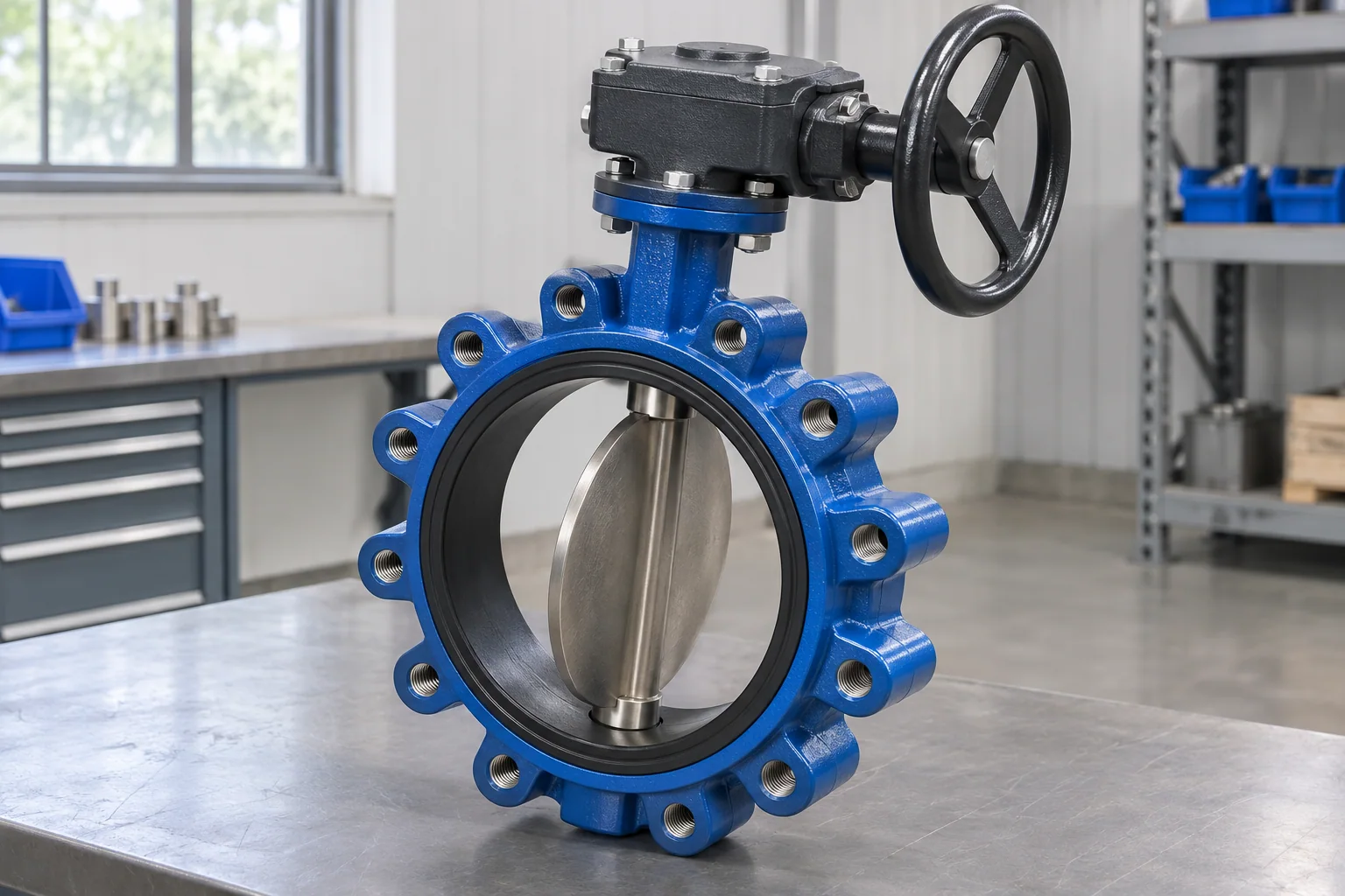
Threaded-lug valve bodies for separately bolted flange connections

Our gear-operated lug butterfly range covers nominal sizes from 2 to 12 in. in PN10 and PN16 selections. Threaded bosses around the body accept the bolts from each mating flange. The order identifies the lug connection, operator and service duty together, including any requirement for end-of-line isolation.

Nominal size range
2–12 in. / DN50–300
Pressure series
PN10 / PN16
Mounting
Threaded body lugs
Operation
Gearbox with handwheel

Lug butterfly valve order specifications

Valve bodyLug-style butterfly valve with threaded mounting bosses
Catalog nominal range2–12 in. / DN50–300
Pressure designationPN10 or PN16 for the selected valve assembly
Flange fasteningSeparate flange bolts into the valve-body lugs
OperatorWorm gearbox and handwheel
Catalog temperature band0–100°C, with seat and medium suitability checked for the order
End-of-line dutyOnly a selected model with an explicit applicable duty rating

Lug butterfly valve nominal size series

Match the valve size and DN on every schedule line before selecting the lug and flange details.

Nominal valve size (in.)Nominal DNPN selections
25010 / 16
2-1/26510 / 16
38010 / 16
410010 / 16
512510 / 16
615010 / 16
820010 / 16
1025010 / 16
1230010 / 16

No matching specification. Clear the search to see every row.

Scroll sideways to see every column.

Nominal-size cross-reference within the 2–12 in. catalog range. Pipe OD, lug-thread size and bolt-circle dimensions come from the selected lug-valve drawing.

Line pressure and end-of-line duty are separate ratings

Dead-end duty needs its own rating

The catalog lists PN10 and PN16 valve selections. Removing the downstream pipe can create a different loading and sealing duty; the selected model needs an explicit rating for that arrangement.

Lug drilling follows the mating flanges

The flange standard and nominal size establish the joint to be matched. The valve drawing then identifies the lug threads and bolt layout.

Approvals stay with the actual model

A fire-water, drinking-water or other approved service must be named in the order. We identify the proposed manufacturer, model and required records with that offer.

Threaded lugs, bolt engagement and removal access

Separate bolts from each flange

Each mating flange attaches to the body lugs. This differs from a wafer valve’s long through-bolts and gives the installation its own bolt-length and access requirements.

Correct engagement without interference

The bolt must engage the intended thread length without bottoming or interfering with the opposite connection. Flange thickness and washers form part of that length calculation, so bolt length is worked out for each joint.

A maintenance duty defined before purchase

If one pipe section will be removed while the valve remains in place, identify that condition on the valve schedule. The selected model and installation details must cover the required pressure, direction and supported arrangement.

Space around the gearbox

A valve can fit the flange gap but leave the handwheel against a wall or access platform. The operator drawing is part of the fit check, particularly where the gearbox orientation is restricted.

Lug valve supply for maintainable piping assemblies

Equipment isolation connections

A separately bolted flange arrangement can suit equipment connections that need a defined dismantling plan. The valve’s permitted duty and the supports around the joint still control the maintenance procedure.

Packaged mechanical plant

Skid layouts often constrain bolt access and handwheel position. Including the adjoining flange and equipment envelope helps resolve those interfaces before the valve is packed.

Distributor valve and fastener lines

Different lug threads or flange patterns can sit within the same nominal valve size. Separate stock descriptions for body, pressure designation and connection details reduce receiving and resale errors.

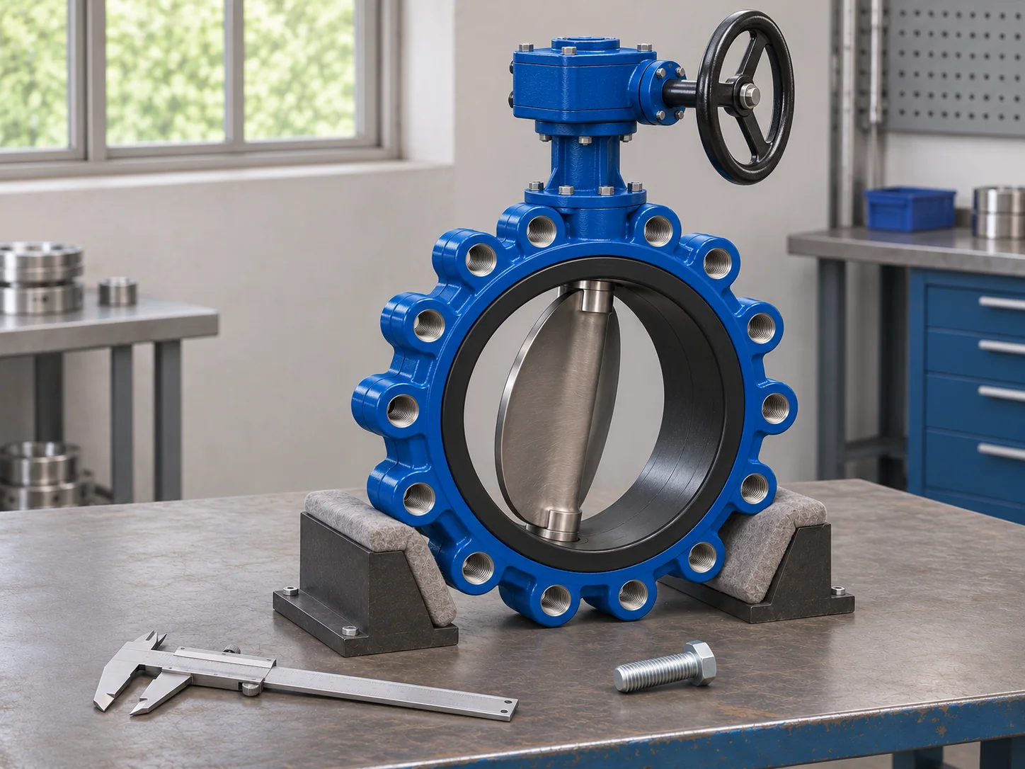
Lug connection and assembly inspection

Lug valve beside a caliper and flange bolt for interface checks

Thread condition at each lug

Damaged starts, contamination and coating in the threads can prevent correct bolt engagement. A bolt forced into a damaged lug can compromise the joint before the valve reaches service.

Disc and adjoining bore

The open disc needs room within the adjoining flange and pipe bore, including any lining or nearby fitting.

Operator and specified indication

Gearbox stops, handwheel movement and position indication belong to the supplied assembly check. Any switch package is identified separately so the receiving team knows what the valve line includes.

Records matched to the ordered duty

The selected model, size and pressure designation need to agree across the drawing, required test records and item identification. An end-of-line requirement must be supported by the offered model’s applicable documentation.

Documents for the installed joint

Lug-thread drawingOperator envelopeRequired test recordsModel and duty identification
Bulk lug valve orders and protected connections

Itemized flange fasteners

We quote the valve-and-gearbox assembly separately from mating flanges, bolts, washers and other connection items. Where fasteners are included, their thread and length stay tied to the selected valve drawing.

Thread and seat protection

Packing protects the lug threads from impact and debris while bore covers shield the seat and disc. The body is supported so the gearbox and handwheel stay clear of load-bearing contact.

Order tags through to receiving

Size, body style and project item reference stay with the valve line and packing list. The quotation states the agreed batch quantities and shipment terms for the destination, without substituting a general catalog lead time.

Lug mounting compared with wafer clamping

Choose the body connection that fits the installation and its planned dismantling method.

DetailLug bodyWafer body
Flange fasteningBolts from each flange engage body lugsThrough-bolts clamp both flanges around the body
Bolt selectionThread form and engagement length are criticalLength follows the full flange/valve stack
One-side pipe removalRequires the model’s applicable duty rating and arrangementDo not remove the clamping needed to retain the valve
Fit drawingLug layout, threads, face spacing and disc sweepLocating arrangement, seat faces and disc sweep

Chemical compatibility, pressure-temperature limits and product approvals are specific to the supplied valve assembly.

See wafer butterfly valve details

Lug butterfly valve order questions

Does a lug butterfly valve always permit downstream pipe removal under pressure?

No. Threaded lugs alone do not establish end-of-line capability. That duty needs an applicable rating for the selected valve model, pressure and direction, together with the manufacturer’s specified installation and support arrangement.

Do lug valves need separate pipe supports?

The valve body and gearbox are not substitutes for pipe supports. The installation arrangement must carry the connected pipe loads without forcing the valve into alignment; allowable external loads and support points follow the selected valve instructions and piping design.

Are the lug threads NPT pipe threads?

Lug holes take flange fasteners; they are not process-pipe connections. Use the bolt-thread specification on the selected valve drawing. Do not choose fasteners from the nominal pipe size or assume a particular inch or metric pitch.

Is a PN16 lug valve the same as a Class 150 valve?

The designations describe different rating systems and should not be treated as interchangeable. Flange drilling may be available to a named pattern, but the valve pressure-temperature limits and the required connection must both match the order.

Can you supply a valve without a monitoring switch?

Yes. The gear-operated valve and handwheel can be itemized as the valve assembly. If electrical monitoring is needed, its switch, bracket and contacts are a separate specified package; they are not implied by the gearbox.

Should a resilient-seated lug valve always have a separate gasket on each face?

Follow the installation instructions for the selected seat and body design. Some resilient seats form the flange seal and do not use additional gaskets. Adding a gasket without the specified arrangement can change seat compression and interfere with operation.

Quote the lug valves and connection details together

Send your valve schedule, flange standard and service conditions. Include any planned one-side pipe removal so the proposed assembly and its duty documentation can be reviewed with the order.

Metdax
Get a quote
Search Metdax

Language

Get a factory quote

Send your specifications or attach a material list.

Lug Butterfly Valve

Your information is used to respond to this inquiry. Privacy policy

sales@metdax.com

+86 177 7599 6440