Key takeaways
Specify the joint before choosing the pipe end
Plain, beveled, threaded and grooved describe how a pipe end is prepared. They do not identify the material grade or corrosion protection. A galvanized pipe can still need a specific thread or groove, and a black pipe can arrive plain or prepared for welding. Keep the pipe specification, end preparation and finish as separate fields in the material schedule.
Start with the mating component and its required duty. Identify the preparation at each pipe end separately; one plain end and one threaded end is different from two threaded ends. Count separately supplied couplings or fittings as their own items.
| Mating component | Pipe-end requirement | Controlling information |
|---|---|---|
| Butt-weld fitting | Specified welding-end preparation | End-preparation standard or drawing, mating wall and joint detail |
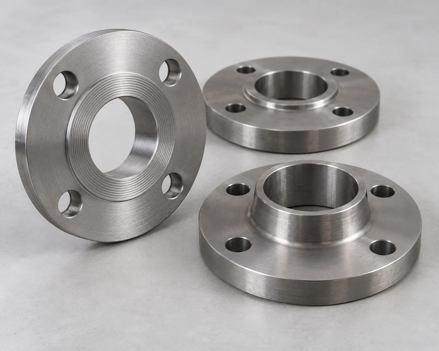
| Threaded valve or fitting | Exact matching thread system | NPT or the specified ISO 7-1 R/Rc/Rp forms, nominal size and joint-sealing requirements |
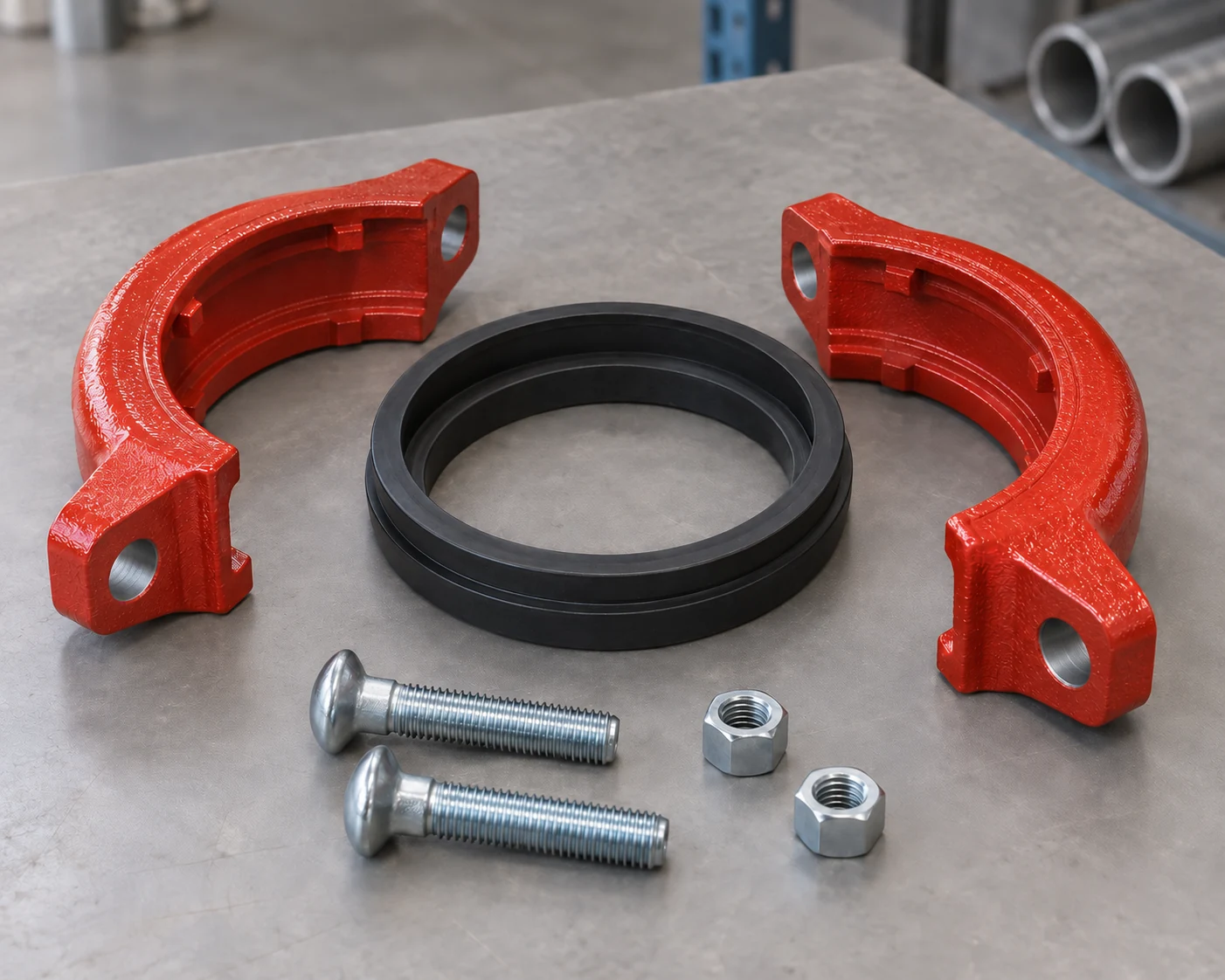
| Grooved coupling | Groove prepared for the selected system | Pipe OD and wall, groove profile, gasket and coupling instructions |
| Pipe blank for local fabrication | Plain end or stated shop preparation | Cut length, retained machining allowance and work completed locally |
Plain ends and welding bevels serve different preparations
A plain end is unthreaded and ungrooved. A square cut describes the end face; it does not supply the bevel, root face or internal transition required by a particular butt-weld joint. For a prepared weld end, state the governing end-preparation standard or drawing and the mating pipe wall. ASME B16.25 addresses welding bevels and internal and external shaping at buttwelding ends.
The welding procedure determines the completed joint preparation and fit-up. One bevel description should not be applied across every wall thickness, root-pass method and backing arrangement. Where the fitting bore and pipe bore differ, identify the transition detail before machining. Our butt-weld pipe fittings should be specified alongside the pipe dimensions, rather than ordered from nominal size alone.
For pipe that will be cut and welded in the fabrication shop, define which preparation is supplied by the factory and which is completed locally. This keeps cutting allowance, temporary protection and the final weld surfaces clear in the quotation.

NPT and BSPT are separate thread systems
R, Rc and Rp Have Different Forms
NPT uses a 60° thread angle; the ISO 7 thread form associated with BSPT uses 55°. The NPT and ISO 7 R/Rc forms compared in this table are tapered. ISO 7-1 also includes Rp parallel internal threads. Equal size names or a matching pitch do not make NPT and ISO 7 joints interchangeable. At 3/4 in. both have 14 threads per inch. At 1 in., NPT has 11.5 threads per inch while BSPT has 11.
Specify the exact ISO 7-1 form: R is a tapered external thread, Rc a tapered internal thread and Rp a parallel internal thread. Rp is part of the thread-sealing ISO 7 system; it is not a generic ISO 228 G-thread substitution. For NPT, retain the specified NPT designation. Check diameter, pitch and form with the appropriate inspection method. A fitting that starts by hand does not establish compatibility.
Swipe to see every column.
The Table Compares the Tapered Forms
| Characteristic | NPT | ISO 7 R/Rc (tapered forms) |
|---|---|---|
| Thread angle | 60° | 55° |
| 3/4 in. nominal size | 14 TPI | 14 TPI |
| 1 in. nominal size | 11.5 TPI | 11 TPI |
| 1-1/4 in. nominal size | 11.5 TPI | 11 TPI |
Match the groove to the selected coupling
Roll grooving forms the pipe wall without removing metal. Cut grooving removes material from the outside surface. The choice affects the wall at the connection and must suit the pipe material, wall thickness and coupling system. A request for grooved pipe is incomplete without the groove profile and the fitting manufacturer's preparation requirements.
The connection checks include actual OD, roundness, end squareness, gasket seating surface and the groove geometry. A groove's width and diameter must match the intended coupling; a general pipe-size table cannot replace that system's dimensional limits. Lined pipe also needs a preparation method that preserves the required internal coating at the joint. Keep coating thickness and any end flare in the dimension check.
Order the pipe and grooved fittings and couplings as a coordinated connection set. State whether couplings are supplied separately or with the lengths, and identify the required gasket material. Similar-looking housings and grooves do not establish the same service rating or installation requirements.
Define the coating system and where it stops
Black describes the product's finish, not a complete coating specification. Bare steel, a temporary oil or varnish, and a permanent protective coating have different purchasing and preparation requirements. For a painted or coated product, state the surface preparation, coating system, required thickness and whether the inside, outside or both surfaces are covered. Color alone does not describe that system.
Joint areas need separate instructions. Welding ends may require a defined coating cutback, with protection during transport and a specified repair system after joining. Threads, grooves and gasket seats need the finish permitted for the chosen fitting. A thick coating applied across a connection surface can alter the dimensions needed for assembly.
Our coated steel pipe range is therefore ordered by the complete coating description and end treatment. For black steel pipe, keep any temporary protective treatment visible in the order so the fabricator knows what must be removed before further finishing or welding.
Coordinate galvanizing with threads and later painting
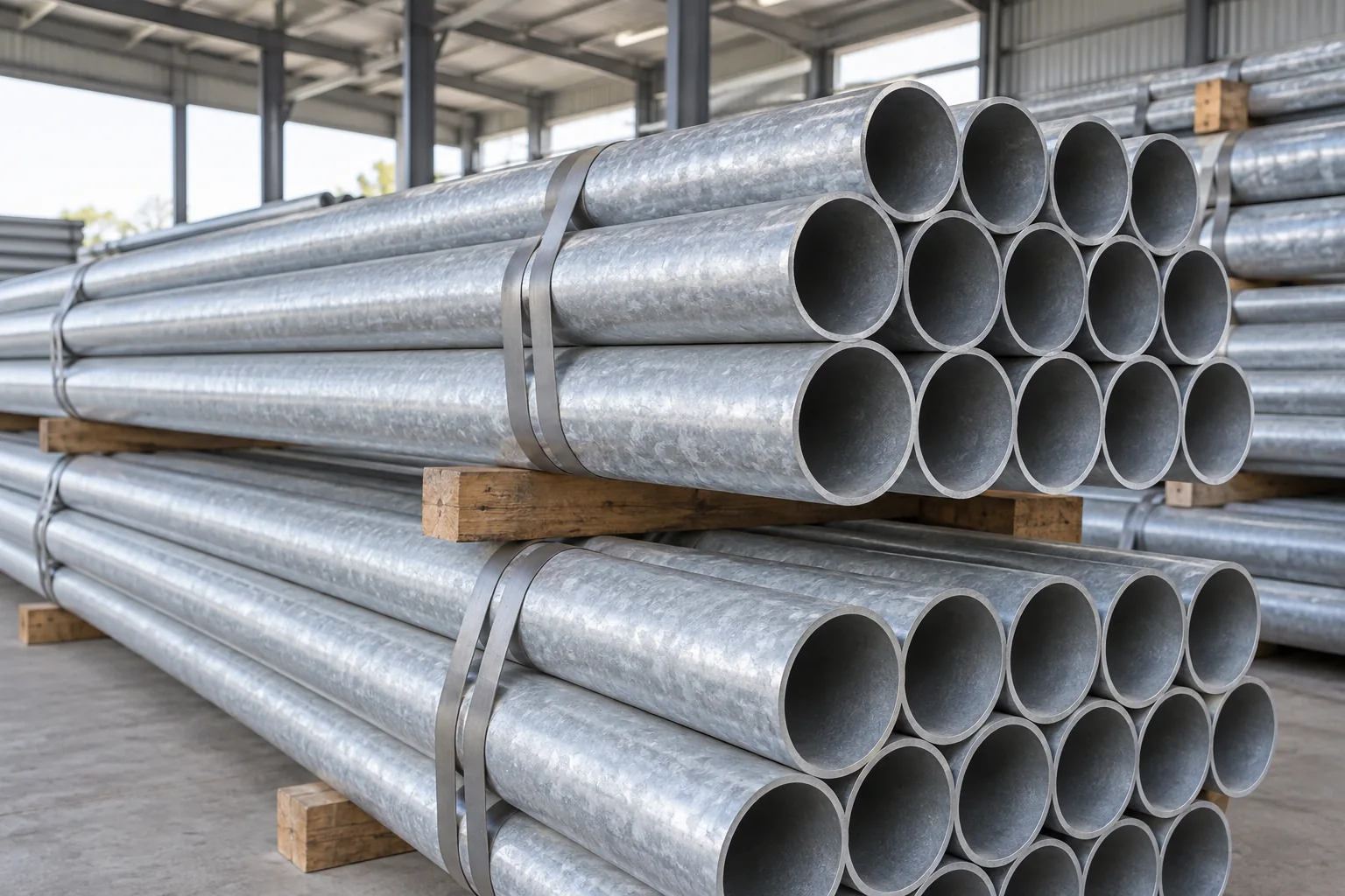
A galvanized finish needs its own applicable specification and coverage requirements. The purchased product may be galvanized as finished pipe, fabricated components or an assembled structure; those forms should not inherit one another's coating acceptance rules. For a threaded item, specify the finished thread and coupling arrangement as part of the galvanized product description.
Painting over hot-dip galvanizing creates a duplex coating system. Adhesion depends on preparing the zinc surface for the selected paint. ASTM D6386 addresses this preparation; powder coating uses the separate practice ASTM D7803. Tell the galvanizer about the later finish before processing, because post-treatments can interfere with adhesion.
Identify who supplies the surface cleaning, profiling and final coating, along with any preparation at cut or processed ends. Our galvanized steel pipe specification belongs in that coordinated order. A bright or dull appearance alone does not establish paint readiness, coating thickness or the condition of the zinc layer.
Inspect connection surfaces before protecting the ends
A finished pipe needs checks at the areas the joint actually uses. For threads, identify the specified gauge check and visible damage at the crest or entry. For grooves, record the system dimensions and the gasket-seat condition. For welding ends, check the prepared geometry and clean surfaces against the drawing. Keep these results tied to the relevant line item or batch, rather than treating one general photograph as inspection of every size.
Packing then protects the prepared surfaces. Thread protectors, end caps, supports and separation need to suit the pipe and finish; they serve different purposes. Identify where the lifting and strapping arrangement could abrade a coating. Newly galvanized products also need drainage and ventilation during storage, because retained moisture between closely stacked surfaces can cause wet storage stain. Coating appearance and remaining coating condition should be assessed separately if staining develops.
Before placing the order, combine the pipe dimensions, end standard, mating fitting, coating coverage, cutback and end protection in one schedule. The sizes, schedules and weight guide covers the dimensional description. Use the buying and inspection guide to align these requirements with documents, quantities and receiving checks.
- End preparation at each end and its governing standard or drawing
- Mating fitting identity, connection profile and gasket or sealing requirement
- Inside and outside coating coverage, thickness and cutback
- Connection-specific inspection and finished-surface protection
Frequently asked questions
Can NPT and BSPT connections be mixed if the fitting starts by hand?
No. Starting by hand does not establish a correct match. NPT and BSPT have different thread forms; identify the specified system, diameter, taper and pitch before matching the pipe and fitting.
What information does a grooved-pipe order need?
Identify the selected coupling system, groove profile, pipe OD and wall, gasket material and required end preparation. State whether the couplings are separate items or supplied with the pipe lengths.
What should I specify when galvanized pipe will be painted later?
Name the later paint system and the zinc-surface preparation, and tell the galvanizer before processing. ASTM D6386 addresses preparation for painting; powder coating uses ASTM D7803. Keep responsibility for cleaning, profiling and finishing visible in the order.
Can plain-end pipe be used unchanged for every welded joint?
Weld-end preparation follows the pipe wall and approved joint detail. Some welds use a specified bevel, root face or other preparation; a plain-end description does not include that work automatically.
Can external coating cover the prepared weld bevel?
Weld-end coverage and cutbacks follow the specified coating and welding requirements. The schedule identifies the area reserved for welding and any protection needed before installation.
Does a grooved joint use the same gasket for every fluid?
The gasket compound follows the actual fluid and temperature requirements for the selected coupling. Coupling size and groove fit are separate from the seal material’s service suitability.
Technical Basis and Source Scope
Technical basis: ISO 7-1:1994, scope and thread-designation symbols R/Rc/Rp; ASME B1.20.1 NPT system; Swagelok Thread and End Connection Identification Guide, tapered-thread tables, for the limited TPI examples. Component-specific groove or seal requirements remain attached to the actual joint.
ISO 7-1:1994 official record — Current official standard identity; ISO records confirmation in 2026.
Galvanized-surface preparation: ASTM D6386-22, public Scope 1.1 and Significance and Use 4.1, addresses liquid painting; ASTM D7803-25, public Scope 1.1–1.1.2, addresses powder coating. These practices concern the stated hot-dip-galvanized products and exclude sheet/coil coating processes. No full paid procedure is reproduced.