Home » Products » Construction & Infrastructure Products » Ringlock Standards

Ringlock Standards Manufacturer

Galvanized vertical members with the rosette and stacking interface matched

We supply ringlock vertical standards for scaffold manufacturers and contractors buying defined components. Tube length, wall, rosette arrangement and top spigot stay together as one member specification. The standard is quoted as a vertical component, with the connecting ledgers and bracing identified separately.

Member
Ringlock vertical standard
Catalog tube OD
48.3 mm
Shown wall
3.25 mm
Shown lengths
0.5–3.0 m

Vertical ringlock member specifications

ProductTubular vertical standard with welded ringlock rosettes
Published tube OD48.3 mm for the selected table
Selected table wall3.25 mm
Length series shown0.5, 1.0, 1.5, 2.0, 2.5 and 3.0 m
Stacking connectionMale joint/spigot and retaining arrangement to the member drawing
SurfaceGalvanized finish with the required coating and acceptance scope

Ringlock standard lengths and theoretical pole weights

The catalog lists theoretical pole weights at 3.25 mm wall. Joint parts and the final assembly weight keep their own order basis.

Member length (m)Tube OD (mm)Table wall (mm)Theoretical pole weight (kg)
0.548.33.252.25
1.048.33.254.51
1.548.33.256.76
2.048.33.259.02
2.548.33.2511.27
3.048.33.2513.53

No matching specification. Clear the search to see every row.

Scroll sideways to see every column.

Selected vertical-standard catalog entries give theoretical pole weights at 3.25 mm wall. The catalog lists the joint separately. The quotation identifies included joint pieces and the final assembled or shipping weight basis for the ordered member drawing and parts.

Component specification and system use

Member drawing

The replacement-member drawing identifies the rosette, tube, spigot and retaining arrangement alongside its length. Those interfaces establish the complete component required for the retained system.

Material and welding

Tube material and welded rosette connections follow the component specification and inspection scope. The complete scaffold design establishes capacity using the accepted components and connection requirements.

Scaffold design and acceptance

The scaffold-system design sets bay capacity, erection height, bracing and anchorage. The component order follows that arrangement and its applicable project requirements.

Rosettes, spigots and vertical continuity

Rosette locations

Rosette levels coordinate the horizontal connections along the standard. Their spacing and orientation follow the member drawing so the required ledger and brace levels line up.

Stacking fit

The spigot and receiving tube form the vertical stacking interface. Diameter, insertion length and clearance are checked together against the selected connection detail.

Retaining pins

The pin or retaining arrangement is a separate connection detail. Hole position and the specified retainer must suit the selected joint; loose hardware is counted separately when supplied.

Galvanized joint surfaces

The finish must leave mating surfaces and holes usable for assembly. Coating acceptance and final fit are considered together where the spigot or pin passes through a close interface.

Vertical standards for component supply and replacement

Scaffold manufacturing orders

Manufacturers can buy a defined length mix with rosettes and stacking interfaces retained on the approved component drawing. Member quantities and the required finish remain explicit on the order.

Replacement vertical members

Replacement orders match the retained system’s rosette, ledger-head, stacking and retaining interfaces. The complete member detail identifies the compatible standard for that scaffold family.

Vertical-member geometry and weld checks

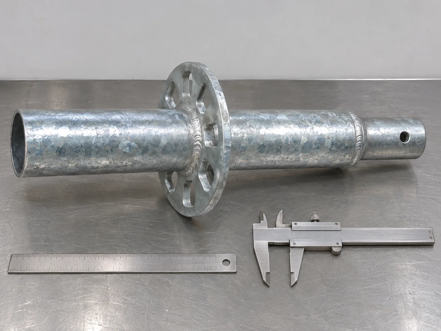
Ringlock standard section beside a ruler and caliper

Tube and member dimensions

Checks cover the ordered tube OD, wall, member length and end condition. The assembled member dimensions are distinguished from the cut-tube dimensions used during manufacture.

Rosette position

The rosettes are checked for their specified location, orientation and connection geometry. Distortion that obstructs the matching ledger head is addressed before release.

Spigot and pin fit

Stacking and retaining details are compared with the selected drawing. Required fit checks use the identified mating component and finished interface.

Finish and weld condition

The release scope covers the specified welded connections and protective finish. Openings, spigot ends and rosette holes remain clear of damage or coating obstructions.

Vertical standard release records

Component drawing and material recordsDimensional and joint checksSpecified welding/finish recordsLength-by-length packing list

Packing a usable length mix

Separated member lengths

The shipment groups standards by length and identifies the piece count in each group. This helps the receiving team reconcile a mixed length schedule before assembly work starts.

Protected connection parts

Supports and restraints avoid using spigots or projecting rosettes as hard contact points. Pins and other loose retainers are identified separately when included.

Component quote lines

Our offer states the vertical member drawing, length, tube specification, finish and quantity. Other ringlock components and freight terms remain separate, clearly identified lines.

Ringlock Standards purchasing questions

Does the table weight include the separate stacking joint?

The catalog lists the 38 × 4 × 270 mm joint separately at 0.9 kg. The pole table uses its published theoretical-weight basis, while our offer itemizes included joint pieces and states the final assembly or shipping weight basis.

Can I choose a different wall and retain the same member weight?

Each wall choice has its own tube mass and accepted component specification. The member drawing and quoted weight basis identify the selected wall and corresponding supplied configuration.

Will these standards fit every ringlock brand?

Fit is established against the identified ringlock system. The rosette, ledger-head seating, stacking connection and retaining details are matched together before that component is accepted for the intended family.

Are stacking pins included with the standards?

The offer identifies loose pins and retainers separately. The required pin type, hole arrangement and quantity belong with the selected member connection.

Can I order a mix of standard lengths?

Yes. List the member drawing and piece quantity for each length. Different walls or connection details remain separate items even when their overall lengths match.

How is the scaffold bay load established?

The system assessment uses the complete arrangement, connections, decks, bracing, supports and design requirements. The supplied component records identify the members used in that accepted scaffold configuration.

Get a ringlock standard quote

Send the vertical-member drawing or mating-system details, tube OD and wall, lengths and quantities. Include rosette spacing, spigot and pin requirements, finish and destination. We return a component-specific offer with loose hardware identified.

Metdax
Get a quote
Search Metdax

Language

Get a factory quote

Send your specifications or attach a material list.

Ringlock Standards

Your information is used to respond to this inquiry. Privacy policy

sales@metdax.com

+86 177 7599 6440