Home » Products » Construction & Infrastructure Products » Frame Scaffold Cross Braces

Frame Scaffold Cross-Brace Manufacturer

Paired tubular X-braces selected by member length and frame-lock geometry

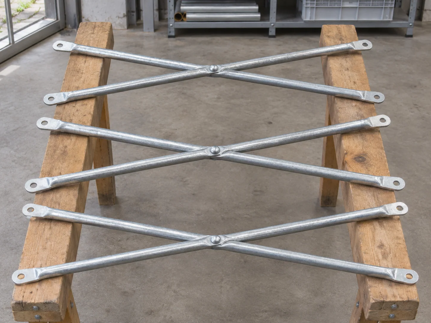
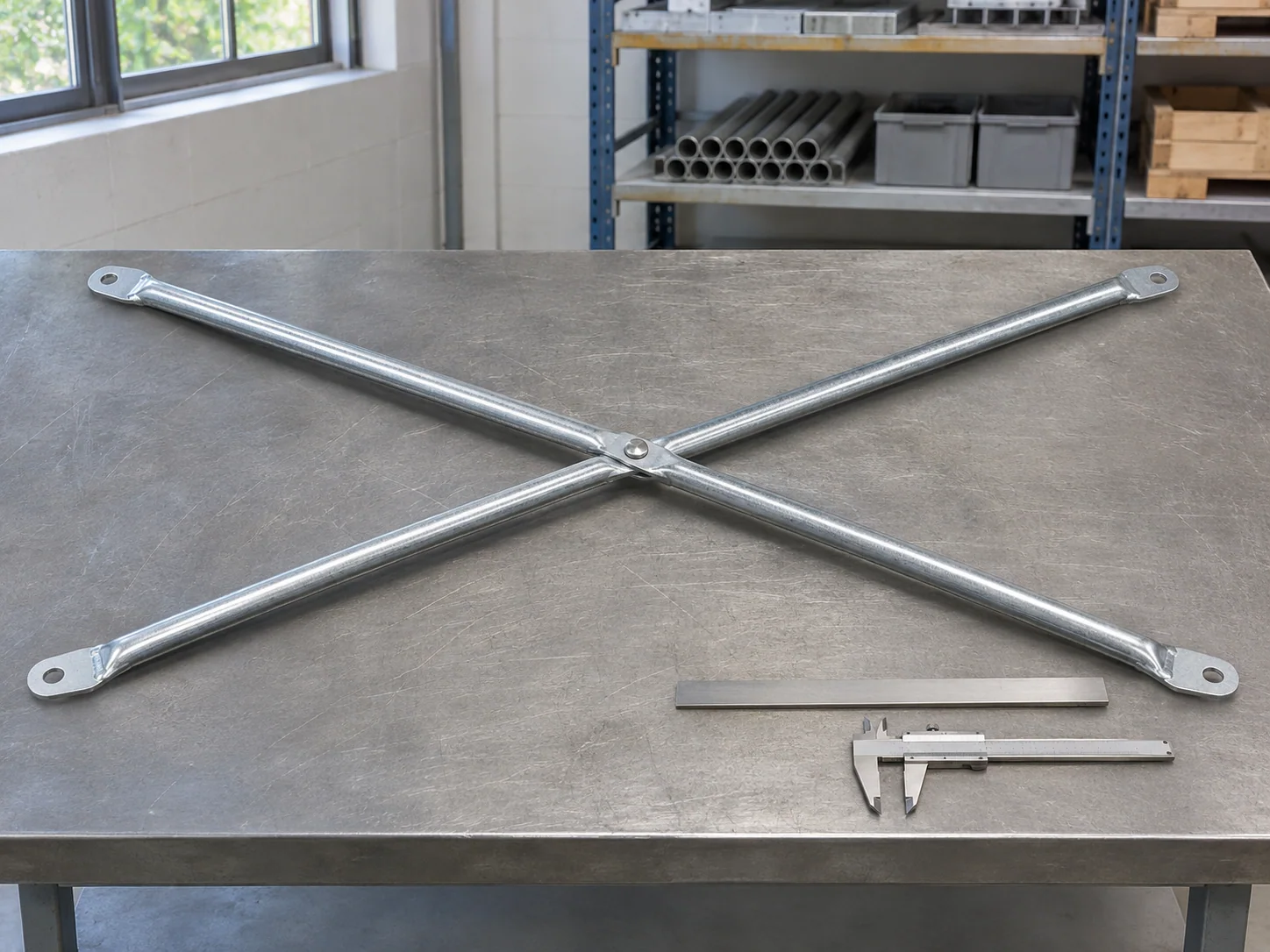
We manufacture paired tubular cross braces for frame scaffolds. Each complete X-brace combines two crossing tubes, a central pivot and flattened connection ends. Our catalog lists 21 × 1.4 mm tubing in four brace-length references, supplied in counted model lots with the end-hole and frame-lock detail retained together.
Tube reference
21 × 1.4 mm
Catalog brace lengths
1,363–2,198 mm
Member format
Paired X-brace assembly
Connection
Flattened pin-hole ends

Complete X-braces and their frame connections

AssemblyTwo tubular arms with a center pivot
EndsFlattened connection tabs with the selected pin-hole detail
Frame matchHorizontal frame separation and vertical lock spacing
Member dimensionsListed brace length plus finished hole-center datums
FinishSelected painted, pre-galvanized or galvanized component route
QuantityComplete paired-brace assemblies by model

Tubular cross-brace length and assembly-mass references

Four dedicated catalog rows use 21 mm outside-diameter tubing and 1.4 mm wall. The listed brace reference and complete paired-assembly mass are kept together.

Tube OD (mm)Tube wall (mm)Listed brace length (mm)Catalog assembly mass (kg)
211.41,3631.90
211.41,7242.35
211.41,9282.67
211.42,1983.00

No matching specification. Clear the search to see every row.

Scroll sideways to see every column.

First-party frame cross-brace catalog references. The selected drawing states the finished end-hole and center-pivot geometry; the receiving frame detail sets the mating lock positions. Listed mass is a component quantity reference for the paired assembly.

Frame spacing, lock spacing and brace-end form

Two spacings establish the brace model

A long bay with closely spaced locks differs from a shorter bay with widely spaced locks. The assembly reference therefore keeps horizontal and vertical spacing together, alongside the measured diagonal and its end details.

End tabs meet the actual lock

The hole, tab thickness and flattened-end shape seat on the specified frame pin and retention mechanism. Those details establish the mating connection for the complete brace, including the finished coating at the contact surfaces.

EN 12811-1 as the design reference

Access and working scaffolds are designed to EN 12811-1, which sets the performance requirements a brace serves within an erected configuration. Prefabricated facade systems carry the additional particulars of EN 12810-1 and EN 12810-2. The adopted standard and erection drawing select the brace.

End-hole datums and the center pivot

Four ends on one paired assembly

Both tubes retain their own end-hole locations. Checking the four end connections together relates the paired brace to the intended frame positions and opening geometry.

Pivot position and opening movement

The center joint connects the two arms and allows the assembly to open for its designed bay. Its position, clearance and retained pin or rivet follow the paired-brace drawing.

Flattened ends and finished surfaces

The transition from round tube to flattened tab carries the specified end profile. Hole edges, tab flatness and finish are checked at that connection detail before the assemblies are grouped for packing.

Brace-only orders and identified frame fleets

Replacement lots by connection rectangle

An existing brace and the frame’s lock positions establish a useful matching reference. We retain that model identity with the complete paired assembly, so different end patterns remain separate order items.

Brace quantities alongside frame quantities

A frame takeoff and a brace takeoff have their own piece counts. Complete X-braces are grouped by model; joining pins, platforms and base components retain separate entries where the order includes them.

Paired-brace dimensions and end fit

Brace length and end-hole checks

Arm and connection measurements

Listed member length, end-hole positions and the pivot datum are checked against the assembly drawing. The four ends retain their intended relationship in the opened configuration.

Finished pin-hole seating

A frame-lock reference checks the selected tab and hole configuration. The finished surface and required retention clearance are included in that connection fit.

Model and complete-piece counts

Each model’s paired assemblies are counted together. The record and packing identification distinguish complete X-braces from loose arms or other scaffold components.

Cross-brace component records

Brace model and drawingEnd-hole and pivot datumsFrame-lock referenceRequired finish checksPaired-assembly count

Complete X-brace prices and compact packing

A price per paired assembly

Our offer lists each brace model, finish and number of complete paired assemblies. The center joint and included end configuration stay with that component line.

Folded assemblies with protected ends

The paired braces are grouped compactly with their connection tabs protected from damaging restraint contact. Bundles retain the selected model and piece count.

Receiving groups for each frame family

Different lengths or mating details have separate groups. The packing list links those groups to the agreed frame-family reference and the order’s shipment terms.

Frame cross-brace purchasing questions

Does one X-brace mean one tube or two?

One complete paired X-brace contains two crossing tubes connected at their center pivot. The quotation uses complete assembly pieces as its quantity unit.

Is the folded shipping length the open scaffold-bay length?

The folded assembly has its own handling envelope. Open-bay geometry is identified by horizontal frame separation, vertical lock spacing and the member’s finished end-hole positions.

Can frame height alone identify the replacement brace?

Frame height helps identify the family. The replacement also retains the actual lock positions, end-hole detail and intended frame separation, which establish the paired brace’s connection geometry.

How do we specify a different end-hole pattern?

Provide the retained frame-lock detail and the required end-hole positions. The revised assembly drawing identifies the chosen tabs and hole centers together with its member and pivot dimensions.

Can we request a matching sample first?

A sample can be specified for the identified frame and brace references. The agreed checks cover the opened connection geometry, end seating, pivot movement and finish before the production lot is released.

How many X-braces are counted for a bay braced on both faces?

Where the released layout shows one complete X-brace on the front face and one on the rear, that bay uses two paired assemblies. Apply the same face-by-face count to the actual bracing plan; each paired assembly remains one purchase item.

Related guides and order tools

Get a frame cross-brace offer

Send the brace references and complete-assembly quantities with horizontal/vertical lock spacings, the end-hole or mating-frame detail, finish and destination. We return a model-by-model brace offer with packing and delivery terms.

Metdax
Get a quote
Search Metdax

Language

Get a factory quote

Send your specifications or attach a material list.

Frame Scaffold Cross Braces

Your information is used to respond to this inquiry. Privacy policy

sales@metdax.com

+86 177 7599 6440