Home » Products » Solar Mounting Systems » Cable-Supported Solar Mounting

Cable-Supported Solar Structure Manufacturer

Tensioned PV arrays with fabricated end frames and matched cable terminations

We fabricate support steel for cable-supported solar mounting, including end frames, intermediate supports and connection pieces. The project’s cable arrangement establishes their geometry and reaction interfaces. Identified cable assemblies, module carriers and termination parts can be itemized with the steel package around the accepted span and tensioning schedule.
Load-bearing form
Tensioned cable array
Steelwork
End and intermediate frames
Cable interface
Matched termination assemblies
Supply unit
Span and zone packages

Cable-supported PV structure supply

Support steelEnd frames, intermediate frames, bracing and fabricated connection plates
Load-bearing cablesSelected rope or strand construction, material and cut-length schedule
Stabilizing systemSpecified cross-connections, stays, restraints or damping components
Cable endsMatched sockets, pins, adjusters and tensioning interfaces
Module carriersSelected cross-carriers and module-retention parts for the stated model
Anchor connectionFabricated head/attachment parts matched to the accepted reaction schedule

Cable construction, stiffness and termination reference

Rope construction and material affect the stiffness used in the tensioning calculation. The FATZER reference below also shows how the termination route changes with the selected cable construction and diameter.

Rope constructionWire materialReference modulus (kN/mm²)Published termination route
Open spiral strand (OSS)Zn95Al5-coated carbon steel160 ± 10Swage: 6–36 mm; spelter: 40–135 mm
Open spiral strand (OSS)Stainless steel 1.4401130 ± 10Swage: 6–36 mm; spelter: 40–80 mm
Full locked coil (FLC)Coated carbon steel160 ± 10Spelter socket
Full locked coil (FLC)Stainless steel 1.4401130 ± 10Spelter socket

No matching specification. Clear the search to see every row.

Scroll sideways to see every column.

FATZER structural-rope engineering reference for the stated constructions and materials. The selected cable manufacturer’s data establishes the rope properties and termination system used in the project calculation. Our package schedule identifies the actual cable, cut length, end fittings and required assembly records.

Cable assemblies and their end connections

Rope construction and material

An open spiral strand and a full locked coil have different wire arrangements and surfaces. The cable selection retains its construction, effective stiffness, breaking-force basis and corrosion system as one identified product.

Swaged and speltered sockets

Swaging forms a matching termination around the cable; a speltered socket uses its specified filling process. The accepted assembly identifies the cable/socket pairing, preparation, fitting dimensions and required termination records.

Pins, forks and adjustment travel

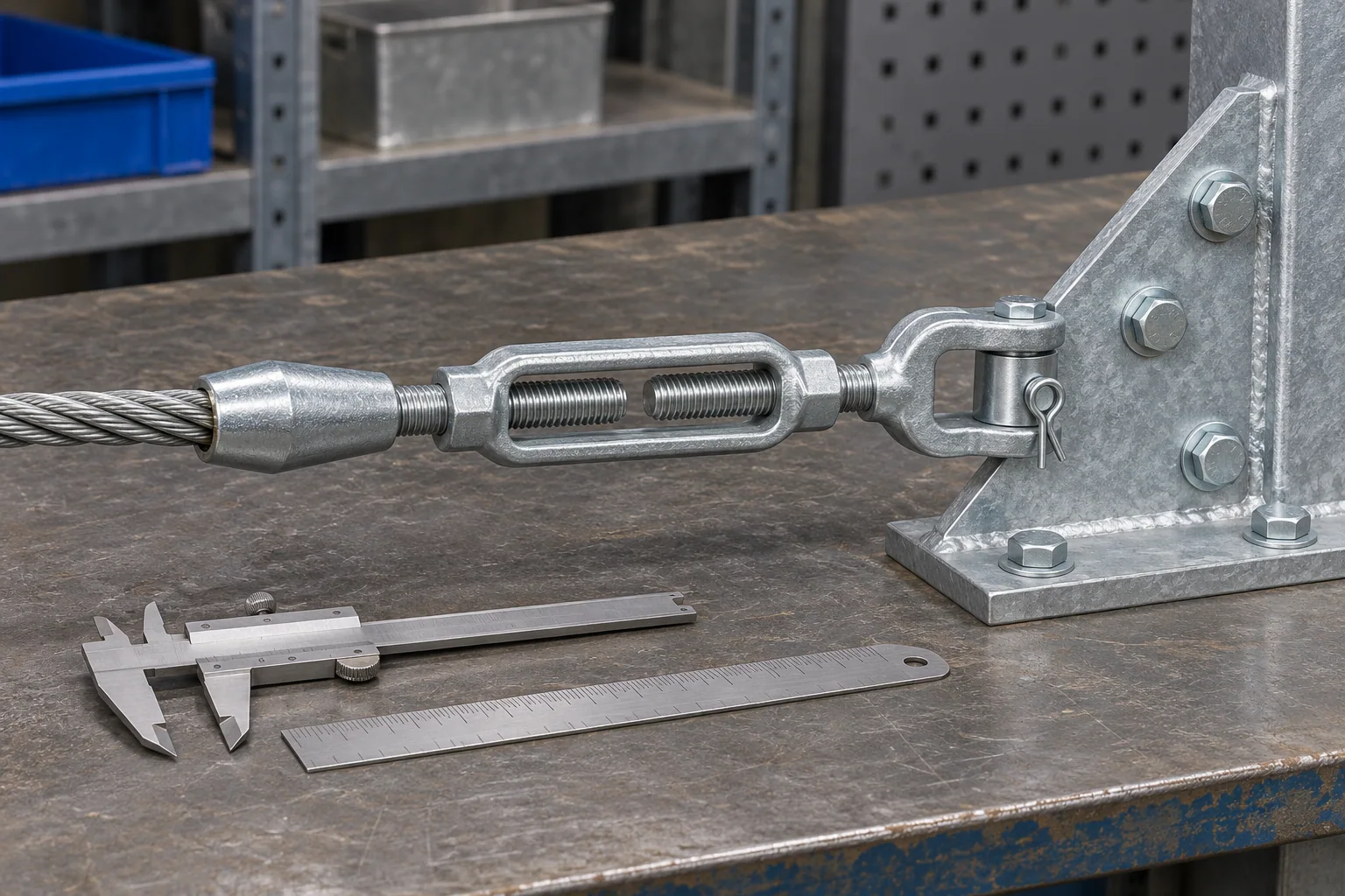
A fork-and-pin connection locates the cable force at the support plate. Pin diameter, fork gap and adjustment travel follow the actual assembly drawing, with room for tensioning, inspection and later service.

Tension components under EN 1993-1-11

EN 1993-1-11 gives design rules for steel tension components that are adjustable and replaceable through their connections to the structure, covering solid round bars and wire-based products anchored in sockets or other end terminations. The structural design selects the cable group, pretension and anchorage.

End frames, anchor reactions and tensioning access

Frames that receive the cable reactions

Cable forces create horizontal and vertical reactions at the end and intermediate supports. Their accepted schedule establishes the frame, bracing and anchor-connection details prepared in our steel package.

Cut lengths and fitted ends

The cable schedule identifies its length datum and termination geometry. Factory-fitted ends and site-completed connections retain their own preparation and inspection steps, including the adjustment position used for assembly.

The tensioning work state

Staged tensioning changes the forces and shape before and after modules are placed. The released sequence identifies the temporary restraints, reference temperature and loading condition for each measured stage.

Open-span PV mounting packages

Arrays with a working space beneath

A cable-supported layout can preserve a defined open zone beneath the modules. The usable height follows the accepted profile under the governing project conditions, including required access and the cable’s movement envelope.

Matched steel and cable packages

End frames, cable assemblies and stabilizing parts can be grouped by span or installation zone. The connection list keeps the module carriers and the end/anchor interfaces attached to their matching assemblies.

Cable identity, measured tension and installed profile

Cable socket, threaded adjuster and loose dimensional tools on an inspection bench

Cables and terminations as matched assemblies

Checks connect the cable material and construction with its termination reference and cut-length schedule. Socket seating, pins, adjustment threads and protective finish remain accessible at the inspection stage.

Measured force with its reference condition

The required tensioning record identifies the cable, method and calibrated equipment with the loading stage and temperature. Accepted corrections or conversions remain linked to the raw reading.

Profile and support survey

Survey checks locate the support points and cable profile against the released configuration. The accepted record connects the measured shape with the corresponding cable state and any approved adjustment.

Cable mounting supply records

Cable and termination scheduleSupport-steel and interface dimensionsSpecified tension/profile recordsMaterial and protection identity

Cable assemblies and support frames packed by span

Protected cable ends

Cable storage and transport follow the selected construction’s bending and handling requirements. Terminations and threads are protected, with matched end fittings retained under their assembly identity.

Steel grouped around the installation sequence

End frames, braces, carriers and loose connection pieces follow the span or zone marks. Cable assemblies and structural parts keep separate counts within that same receiving group.

A defined structural-package price

The offer itemizes support steel, cable assemblies, module carriers and the named connection parts. Specified records, tensioning equipment or site support, packing and shipment terms appear as their own supply lines.

Cable-supported solar mounting purchasing questions

Which PV modules can be mounted on a cable-supported structure?

The selected module’s approved support and attachment details define the carrier connection. Conventional rigid framed modules can be carried by a cable-supported structure where that arrangement is accepted; the module model and mounting configuration remain identified together.

How is a cable tension reading accepted?

Acceptance uses the specified force or permitted range at the named loading and temperature condition. The record also identifies the measurement method and its calibration, allowing the reading to be compared with the same reference state used in the structural design.

When is a tension recheck included after installation?

The project’s installation and maintenance plan sets the recheck stages and event triggers for the selected cable system. Those records retain the original cable IDs, profile stations and reference conditions for a meaningful comparison.

How are adjacent spans connected in the order?

The support and cable drawings identify shared frames, continuous cable routes and any independently terminated spans. Their reactions and tensioning sequence follow that arrangement, and the parts list shows which pieces are shared between the receiving zones.

What changes when a different module model is selected?

Module mass, dimensions, mounting zones and carrier positions enter the cable-system review. The accepted change updates the relevant cable/profile calculation, local attachment and support reactions before the revised package is released.

Can cable assemblies or end fittings be ordered separately?

Identified replacement or partial-package items can be quoted from the retained cable system and drawings. The line identifies the cable construction, mating termination or pin connection, finish and quantity, including the records required for that supplied assembly.

Related guides and order tools

Quote a cable-supported PV mounting package

Send the span layout, module data and required clear zone with the project location and quantities. Include available support/anchor reactions, the cable-system specification and the requested steel/cable supply scope. We return an itemized package with matched interfaces, required records and shipment terms.

Metdax
Get a quote
Search Metdax

Language

Get a factory quote

Send your specifications or attach a material list.

Cable-Supported Solar Mounting

Your information is used to respond to this inquiry. Privacy policy

sales@metdax.com

+86 177 7599 6440