What has to come out during maintenance?
Separate routine cleaning from component replacement
Start with the service procedure, not the coupling catalog. Cleaning a strainer basket, replacing a complete valve and withdrawing a pump assembly require different openings. Mark the part’s starting position, travel direction and final handling space on the layout. Include the route to a lifting point or aisle where the removed part will be taken away.
Preserve the straight pullout path
A basket or cartridge can need a straight withdrawal distance even when its cover is easy to reach. For example, Bell & Gossett’s Suction Diffuser manual A91310M, Installation guidelines and Figure 1, assigns a model-specific removal dimension A. Insulation must also permit access to the removable internals. An accessible coupling nearby does not clear a wall in that path.
Use a removable spool to create working space
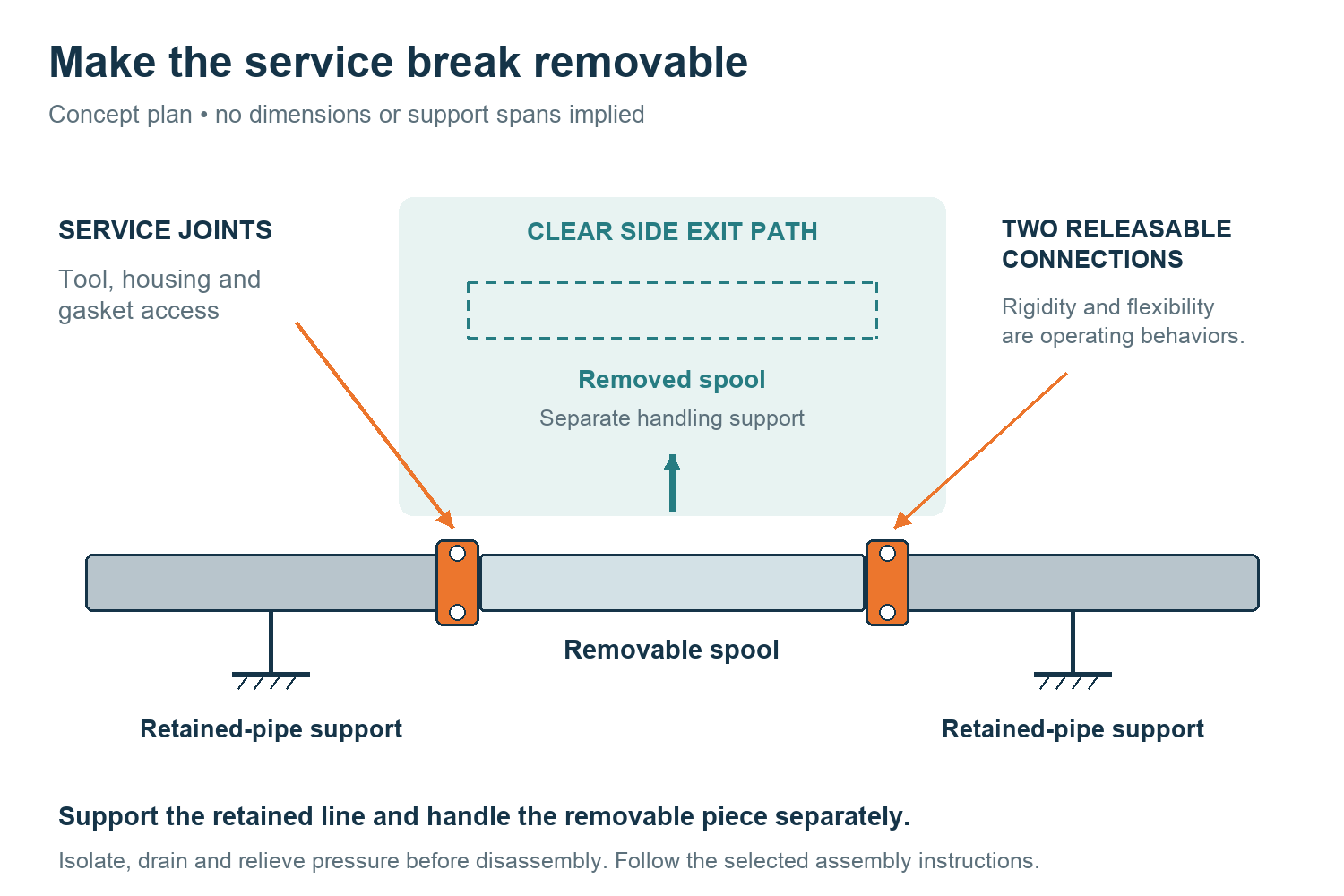
For a whole valve or pump component, identify which joints must open and which neighboring pipes must stay in place. A removable spool—a short, deliberately detachable pipe section—can create an opening beside the equipment. Its usefulness depends on being able to remove the spool itself, including its gasket and housings, before attempting to withdraw the equipment part.
Rigid or flexible couplings at the service break?
Disassembly and operating movement are separate choices
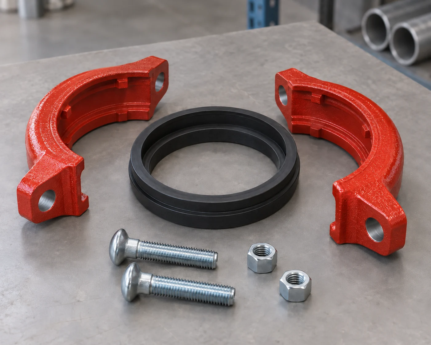
Rigid and flexible describe the assembled joint’s behavior. They do not tell you whether a connection can be dismantled for maintenance. A rigid grooved coupling can be a service connection when its selected installation instructions provide a disassembly and reassembly method. Choosing a flexible version does not automatically make the component easier to extract.
Rigid joints for a line that must hold its geometry
Use a rigid layout where the line is intended to retain its alignment. Victaulic’s Grooved Piping System—Design Data, 26.01 Rev D (©2024), p. 1, describes its rigid joints as having system behavior similar to welded or flanged piping. This still requires a support and thermal-movement design; rigidity at one joint does not make the whole line an anchor.
Flexible joints where movement is part of the design
A flexible coupling supplies limited movement within the selected model’s pipe, groove and installation conditions. Use that capacity for a defined movement requirement. The same design data, p. 2, explains that the full axial and angular capacities cannot both be used simultaneously. Do not count its operating movement allowance as a maintenance telescoping stroke.
Retain the required equipment flange
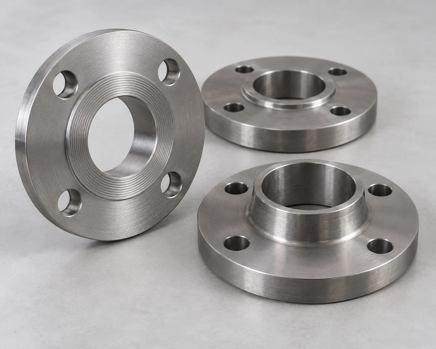
Keep a flanged pump nozzle or flanged valve where that is the accepted equipment interface. A suitable grooved-to-flanged spool can connect it to the grooved line while giving the designer a deliberate service break. Check the complete spool length, flange bolt access and gasket separation; changing the pipe joint does not change the equipment’s removal procedure.
Swipe to view the complete table.
| Maintenance need | Useful configuration | What can defeat it |
|---|---|---|
| Remove a short spool between fixed pipe ends | Two accessible service joints around the spool; rigid joints where no joint movement is needed. | No route for the spool, housings or gasket to leave the space. |
| Accommodate specified movement near equipment | The flexible-joint arrangement accepted for that movement, with its own support and restraint details. | Assuming flexibility replaces the movement calculation or nozzle-load assessment. |
| Disconnect an existing flanged nozzle | Retain the mating flange; place an accessible grooved break in an adjoining removable spool where useful. | Bolts cannot be withdrawn, faces cannot separate or the spool remains trapped. |
| Clean a basket through a service cover | Keep the cover and manufacturer’s internal withdrawal envelope clear. | Couplings are accessible but the basket still meets a wall, cable tray or permanent support. |
Check three separate maintenance clearances
Tool access to every fastener
First check access to the hardware. Leave the selected socket or wrench a workable approach to each bolt pad, including any required hold on the opposite side. Show the installed insulation jacket, actuator and adjacent pipe, rather than reviewing an uninsulated bare joint.
Space to remove and refit the coupling
Next check the coupling’s own disassembly sequence. The housing halves and gasket need a route off the joint. Some gasket designs require space on the adjoining pipe during reassembly; other product instructions use different methods. Do not promise zero axial clearance or assume the pipe can stay perfectly fixed until the chosen assembly’s procedure has been checked.
A continuous route for the part being removed
Finally check the removed part’s full path. Include the length or diameter that sweeps past nearby objects, not just the clearance at the first joint. Victaulic’s Series 731-D suction-diffuser publication 09.20 Rev J, updated August 2025, p. 4, lists a distinct assembly-clearance dimension C alongside support-leg requirements. Its dimensions belong to that product; the point is to preserve the selected equipment’s service envelope independently of the coupling envelope.
What supports the pipe after the joint is opened?
Support the retained line and the removed piece
Review the maintenance condition as well as the operating condition. Once a joint opens, a pipe section may lose a load path that existed in the complete line. Retained piping and equipment need their own support, while the removed piece needs a handling or temporary-support arrangement. Place these so they do not occupy the extraction route.
Victaulic’s 26.01 Rev D, pp. 4–5, covers support, anchorage and guidance. It directs support to adjoining pipe and equipment rather than attaching supports directly to couplings. General straight-run hanger tables do not establish a support arrangement for a concentrated valve or equipment load.
Keep maintenance loads off the pump nozzle
The pump nozzle is not a convenient place to hang the disconnected line. The Bell & Gossett diffuser manual requires support to prevent strain on the pump and says not to use the diffuser as a piping support. In a resilient-mounted installation, include the pump, connected equipment and proposed supports in the movement review. A flexible coupling alone does not define the resulting motion or loads.
Make the service break safe to open
The maintenance procedure must isolate the affected section, lock out the equipment as applicable, cool it, drain it and verify that pressure has been relieved before a coupling is loosened. This is especially important where a valve or a branch can leave trapped pressure on one side of the planned break.
Worked choice: two serviceable spool configurations
The same maintenance task and two qualified layouts
Consider a hypothetical mechanical-room water branch on fixed equipment. A short grooved spool must be removable for access to an adjoining equipment connection. The designer has accepted two arrangements for the same pipe OD and groove, fluid, pressure, temperature, gasket suitability, nozzle loads and thermal behavior. Both have adequate permanent supports for the retained pipe and a documented temporary-handling method.
Both layouts provide tool, housing and gasket access, and both spools can leave through the same clear side aisle without moving the header. For the separate equipment withdrawal, assume 450 mm (17.7 in.) is required along the marked pull direction and 600 mm (23.6 in.) is available from the service face to the first obstruction. The spare envelope is 600 − 450 = 150 mm (5.9 in.). These example dimensions are separate from the lifting and handling space, which is also assumed to have been checked.
Configuration A uses two rigid service couplings around the spool. Configuration B uses two flexible service couplings at the same positions; its setting, guidance and restraints have also been accepted. Both are available by the required date and within budget. The owner wants repeatable alignment, and the current movement design requires no movement at either service joint.
Swipe to view the complete table.
| Decision factor | A: rigid service joints | B: flexible service joints |
|---|---|---|
| Spool connections opened for this task | 2 grooved joints. | 2 grooved joints. |
| Extraction route and equipment pullout | Same accepted side route; 600 mm available against 450 mm required. | Same accepted route and pullout space. |
| Behavior of the assembled service joints | Restricts joint movement and retains line alignment. | Permits the accepted limited movement; settings and restraints remain part of the design. |
| Owner’s present priority | Preferred: matches the fixed-line objective without adding unused joint movement. | Qualified alternative, with no extraction advantage assumed. |
Select the rigid arrangement for this fixed line
Select A. The rigid arrangement delivers the required disassembly access and matches the intended fixed geometry. B is not rejected as unsuitable; its movement capacity adds no benefit to this maintenance task.
When a flexible arrangement becomes the better choice
If the equipment is changed to a resilient-mounted arrangement requiring relative movement at these locations, reconsider B using the calculated motion and its accepted coupling limits, pipe-end settings, supports and restraints. A can no longer be carried over as the answer without a different movement provision. If an obstruction reduces the clear equipment pullout below 450 mm, both illustrated layouts fail that maintenance requirement; changing rigid couplings to flexible ones does not recover the missing space.
Put the maintenance arrangement on the piping schedule
Locate the service break and the part it releases
Identify each service break on the layout and give its purpose: basket cleaning, spool removal, valve replacement or equipment withdrawal. Record the joints to open, the removable component, its handling method and the supports that remain in place. Keep the required pullout direction and the first obstruction visible on the drawing.
Retain the complete joint and equipment details
For the grooved coupling assembly, retain the actual pipe OD, pipe material and wall, groove profile, model, rigid or flexible function, pressure-temperature basis, gasket and compatible hardware. Attach the selected disassembly and reassembly instructions. A spare gasket is identified by assembly and service, not just a nominal pipe size.
Where the break serves a pipeline pump, keep the final nozzle interface and equipment service drawing with it. A later change in coupling housing size, flange length, insulation or actuator orientation can reopen access even if the nominal pipe size stays the same.
Frequently asked questions
Can a flexible grooved coupling replace a dismantling joint?
Not by name alone. A flexible coupling’s permitted in-service movement is not a guaranteed telescoping distance for equipment removal. If a dismantling joint is specified to create axial withdrawal space, compare that complete function with the proposed grooved arrangement, including its disassembly path and restraints. A removable spool may provide access, but it is a different layout solution.
Must a removable spool have a coupling at both ends?
It needs releasable connections at the ends that must separate. Two accessible grooved joints are one arrangement; a flange at one end and a grooved joint at the other may suit the equipment. A coupling at only one end will not release a spool whose other end remains welded or otherwise fixed. Include any adjoining flange that must open in the maintenance plan.
Can coupling bolts face the wall if the joint was installed before the equipment?
Only if the completed installation still provides the required maintenance access. Construction access can disappear after equipment, insulation or cable trays are installed. Check the selected tool and the complete fastener removal route in the finished room; rotating a bolt pad is useful only when the model and surrounding arrangement permit it.
Can the existing gasket be reused after maintenance?
Use the selected coupling’s reassembly instructions and inspect the gasket, housing and hardware as directed. Reject damaged or unsuitable parts and use the specified gasket and lubricant for the service. Do not turn a manufacturer’s conditional reuse procedure into a promise that every gasket can be reused after every opening.
Does removing the insulation solve a blocked service path?
A removable jacket can restore tool or housing access that the insulation covered. It does not remove a permanent pipe, wall or support in the component’s withdrawal path. Show which insulation pieces are removable and review the remaining equipment envelope before accepting the layout.
How should maintenance spares be specified for grooved service joints?
Record the coupling manufacturer, model and size; actual pipe OD and groove; gasket grade and service; and specified hardware. Keep the applicable instruction revision with the maintenance record. Similar-looking housings, seals or bolts from another assembly should not be treated as interchangeable without explicit compatibility confirmation.
Technical Basis and Source Scope
Victaulic, Grooved Piping System—Design Data, publication 26.01, Rev D, ©2024: p. 1 rigid-joint behavior; p. 2 movement interaction; pp. 4–5 support, anchorage and guidance. Product-specific design reference; no universal support spacing is prescribed here.
Victaulic, Suction Diffuser Series 731-D, publication 09.20, Rev J, updated August 2025: p. 4 ANSI Class 150 assembly-clearance and support-leg table. Used to distinguish equipment service clearance from coupling access, not to rate another product.
Bell & Gossett, Suction Diffuser Instruction Manual A91310M: printed pp. 7–9, Installation guidelines, Figure 1 and dimension A; printed pp. 11–13, servicing. The stated access and support instructions apply to the equipment covered by that manual.
Victaulic, Field Installation Handbook I-100, Rev H, March 2023: printed pp. 38 and 40, spacing and support; pp. 116–117, reassembly of Styles 009N, 107V, 107N and 807N. The cited procedures apply to those assemblies; replacement and reassembly requirements must match the installed model.