How weld-neck and slip-on flange joints differ
Butt weld versus overlapping fillet welds
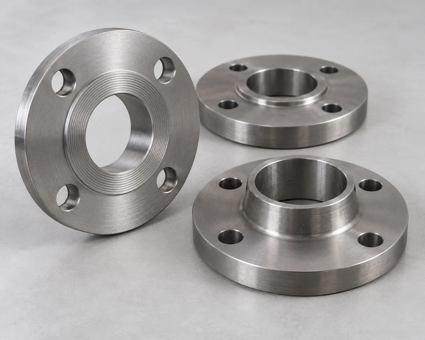
A weld neck ends in a tapered hub that meets the pipe at a butt weld. The pipe does not pass through the flange. Its bore and weld-end preparation must suit the connected pipe wall. A slip-on fits over the pipe outside diameter; the usual hubbed arrangement has an outside fillet weld and a second fillet at the pipe end inside the flange.
The tapered weld-neck hub provides a gradual transition between the stiff flange ring and the pipe. That is a useful reason to consider it for cyclic duty, but it does not establish an allowable number of starts or a universal fatigue-life multiplier. The slip-on overlap offers axial positioning during fit-up, with two weld locations to complete and inspect.
The pump connection remains bolted
The word “weld-neck” describes the pipe attachment, not the bolted joint at the pump. Either flange type can be part of a removable bolted connection. Both still need the correct mating face, gasket, bolt pattern and assembly procedure.
Check the piping class and pump nozzle before comparing prices
Pressure class is one part of qualification
Use the design pressure and temperature, fluid, material group and adopted piping code to establish the flange requirement. ASME B16.5-2025 covers flange ratings, dimensions and related requirements; its public scope is not an approval for a particular pump station. “Class 150” is a class designation, not a fixed 150 psi working limit.

If the piping specification permits only weld necks, a slip-on quote is a substitution request. Where both are permitted, retain the same nominal size, material, pressure class and facing for the comparison. Changing the attachment type alone does not justify a higher pressure-temperature rating.
Match the actual nozzle face
Check the pump vendor’s nozzle drawing separately. A matching bolt circle does not establish a matching facing, gasket arrangement or allowable nozzle load. Record the nozzle standard and face before ordering the mating flange; avoid treating a stock raised-face flange as a universal pump connection.
Where the choice changes after both flange types qualify
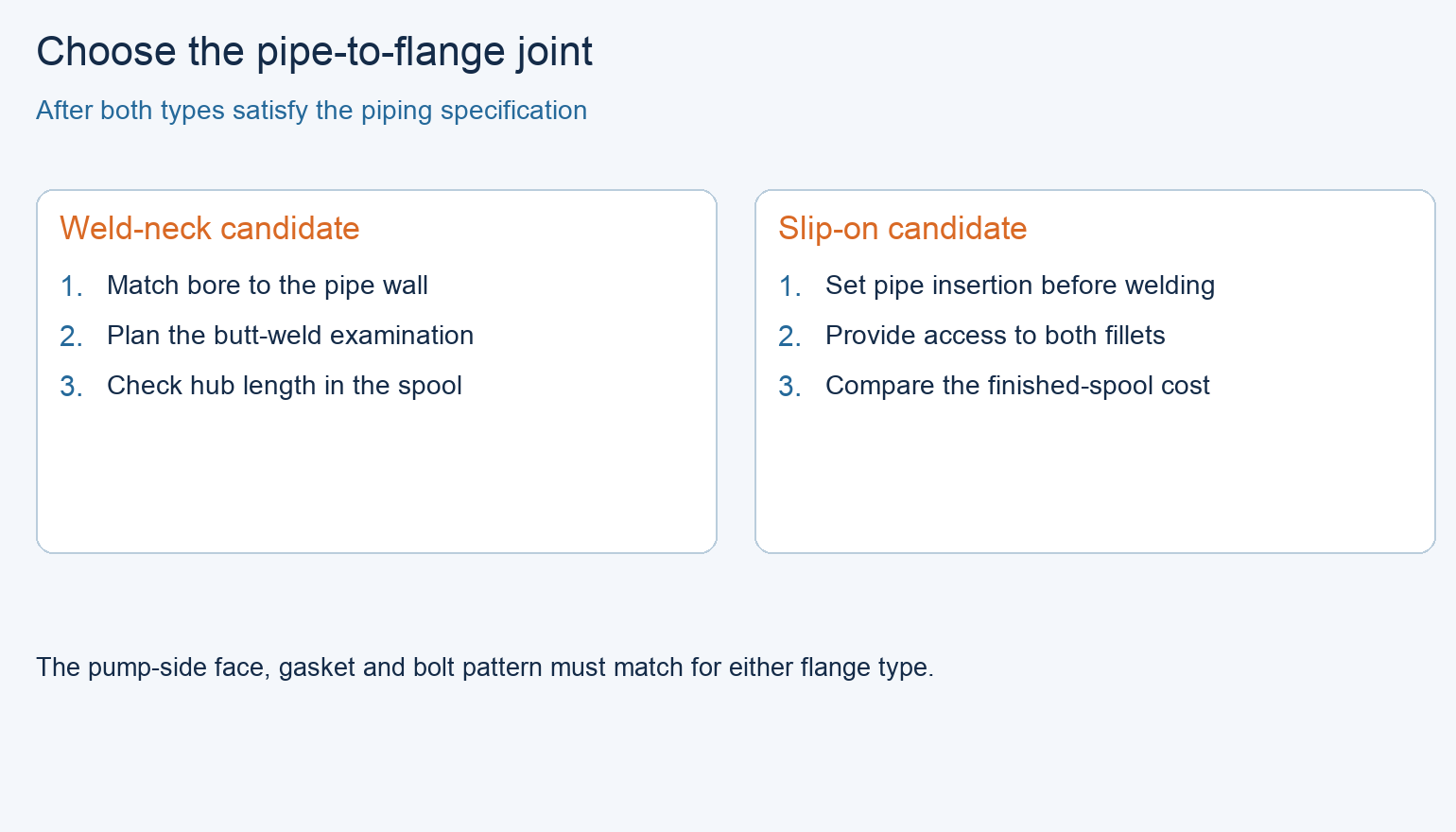
Once the piping designer accepts both options for the duty, compare the shop work and the installed layout on the same basis. The differences below explain why the preferred type can change from one spool to another.
Swipe to view the complete table.
| Decision factor | Weld-neck flange | Slip-on flange | Effect on the order |
|---|---|---|---|
| Fit-up | Prepared pipe end meets the hub at a butt joint | Pipe position can be adjusted within the flange before welding | Compare the actual shop sequence and final face-to-face tolerance |
| Weld access | Access around the butt joint and space for the specified examination | Access to both fillet locations in the usual hubbed arrangement | Do not price only the easiest visible weld |
| Bore selection | Specify the pipe schedule or actual bore at the weld end | Bore clears the pipe OD | A nominal pipe size alone is insufficient for a weld-neck order |
| Repeated loading | Tapered hub avoids the abrupt pipe-to-ring transition | Overlap and fillet geometry differ from a butt joint | Use the accepted stress/fatigue design, not a claimed life multiplier |
| Available space | Hub length affects the spool layout | Shorter attachment geometry may help a tight arrangement | Check drawings; neither type removes bolt and tool access needs |
| Finished cost | Include beveling, fit-up, butt welding and examination | Include both fillets, access and face protection | Compare completed, accepted spools rather than loose flange prices |
Plan flange welding and inspection before spool fabrication
Match examination to the joint
An inspection plan written for butt welds cannot simply be copied onto slip-on fillets. Specify the examination method, extent, acceptance criteria and access for the chosen joint. A weld neck is not automatically subject to 100% radiography, and a slip-on is not automatically exempt from examination; the applicable code and project requirements decide that.
Order the weld-neck bore explicitly
For weld necks, put the connected pipe wall or required bore on the order. For example, the Texas Flange weld-neck bore chart lists NPS 6 pipe at 6.625 in. OD, with nominal bores of 6.065 in. for Schedule 40 and 5.761 in. for Schedule 80. The same NPS therefore does not identify the weld-neck bore. These catalog values illustrate the ordering distinction, not machining tolerances.
For slip-ons, the fabrication drawing must establish pipe setback and weld details. Protect the gasket seating surface during welding and check the finished flange position. Do not improvise a setback dimension from a photograph or use the gasket face as a welding reference without the approved detail.
Keep pipe strain out of the pump nozzle
At installation, support and align the pipe so tightening the flange bolts does not pull the pump into position. Xylem’s Series 1710 manual, sections 4.3 and 4.6, treats piping support and alignment as installation requirements. A heavier flange cannot correct pipe strain.
Worked comparison: two approved water-pump spools
Consider a hypothetical NPS 6 utility-water station. The design has already accepted both flange types in the same material, class and facing, and the pump nozzle loads have been checked. The shop can perform both weld procedures. Two different locations now need a choice; no market prices or service-life estimates are assumed.
Discharge spool: weld neck
For the accessible shop-built discharge spool, the owner wants a butt-weld examination plan and consistent butt-weld construction through the spool. Select a weld neck with the specified pipe bore. The slip-on remains an approved pressure-boundary option, but its different weld arrangement offers no fit-up benefit in this location and adds a separate inspection detail.
Utility bypass: slip-on when the completed quote supports it
For the low-cycling utility bypass, the design permits slip-ons and the layout leaves access to both fillets. Final pipe insertion can be set in the fabrication jig before welding. Select the slip-on if the shop’s completed-spool quote confirms a cost or fit-up advantage. A cheaper loose flange without that fabrication allowance is not enough to choose it.
Reopen the bypass choice if operating duty becomes substantially more cyclic, internal weld access disappears, or the piping specification changes. Reopen the discharge choice if the hub length prevents the approved layout. Resolve those changes in the spool drawing before release; do not substitute at the delivery stage.
What to put on the pump-station flange order
Loose flanges and fabricated spools need different scope
Each line needs the flange type, size, standard and edition, material grade, class, facing and quantity. Add the pipe schedule or bore for weld necks; attach the approved slip-on weld detail for fabricated assemblies. Separate loose-flange supply from completed-spool supply so welding and examination are priced only once.
For a finished spool, add the drawing revision, flange-face orientation, face-to-face dimension, coating limits, examination records and packing protection. Use the accepted pump nozzle drawing at the mating end. The broader pipe ends and connections guide covers how the flange selection fits the rest of the line.
Frequently asked questions
Can a slip-on flange replace a weld neck without changing the pressure class?
It may retain the same class designation, but the substitution changes the pipe attachment. The piping specification, service duty, weld detail and inspection plan must accept that change before purchase.
Does a weld neck make a pump connection maintenance-free?
No. It changes the welded attachment to the pipe. The bolted joint still depends on gasket selection, bolt loading, face condition and correct alignment, and the pump still needs its prescribed maintenance.
Why does a weld-neck supplier ask for pipe schedule?
The weld-neck bore must suit the pipe bore at the butt joint. Different wall schedules can share the same outside diameter but have different inside diameters. Give the actual bore when the pipe does not match the usual schedule dimensions.
Can both slip-on fillets be completed after bolting the flange to the pump?
The internal weld location needs access before the connection is closed. Plan welding and examination in the spool fabrication sequence; do not use the installed pump as a fixture or assume the second weld can be reached later.
Which flange should be used for a vibrating pump line?
First identify the vibration and pipe-loading cause. A weld neck may suit the accepted cyclic-service design, but changing flange type does not repair misalignment, poor supports or unsuitable pump operation.
Which is cheaper for a small replacement spool?
Compare the complete job: flange, pipe preparation, welds, examination, coating repair and installation. Slip-on fit-up can be useful, while a weld neck may match the existing butt-weld specification with fewer changes. Obtain prices for the same accepted scope.
Technical Basis and Source Scope
ASME, B16.5-2025, Pipe Flanges and Flanged Fittings, official Description/Scope: basis for the distinction between flange class, dimensions and piping-code application. The full rating tables and project welding requirements are not reproduced here.
Texas Flange, “How a Slip-On Flange Sits on the Pipe,” “Weld Neck Flanges,” and “Weld Neck Flange Bore Chart,” NPS 6 row: attachment geometry and the two catalog bore values. Xylem, Series 1710 Installation, Operation, and Maintenance Manual, document 90036301_1.0, sections 4.3 and 4.6: model-specific piping support and alignment instructions. Consult the supplied pump manual for its installation details.
The spool choices are editorial comparisons under the stated hypothetical design approvals. They do not assign pressure ratings, weld sizes or allowable fatigue cycles.
