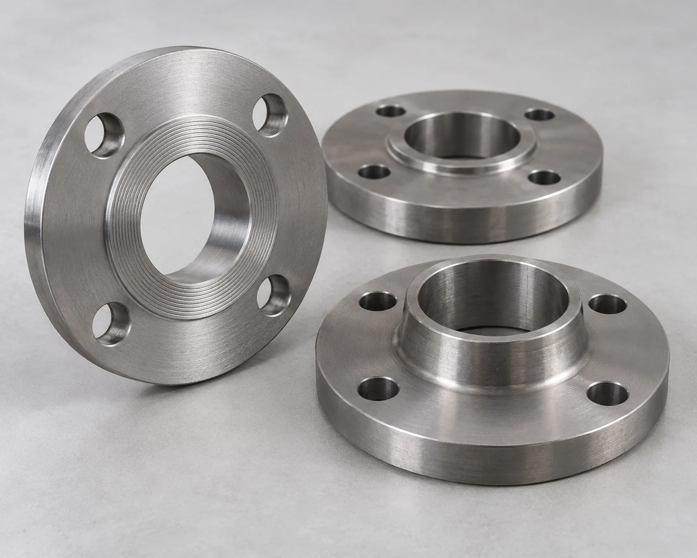
Survey the Existing Flange and the Replacement Pump Together
Identify Rating, Facing and Current Condition
Record the existing connection standard, nominal size, pressure class or rating designation, material, face type and mating dimensions. Compare those details with the replacement pump’s certified nozzle drawing. The same nominal size and bolt pattern do not establish a suitable gasket arrangement or pressure-temperature rating.

Check the condition of the retained flange, its seating surface, bolts and adjacent pipe using the project’s inspection requirements. Original records can identify what was installed, but they do not prove its present condition. If the material, rating or condition remains unresolved, do not label the connection reusable just because it has operated before.
Measure Position as Well as Nominal Size
Measure the nozzle position and orientation relative to fixed site references. Include flange-face separation, centerline offset, bolt-hole orientation and the surrounding obstructions. Tie the survey to the replacement pump’s final location, not an early outline drawing. A nominally like-for-like pump can still have a different connection envelope.
Decide What to Retain, Adapt or Replace
Retain a Suitable Interface
Retain the existing arrangement when its condition, rating, geometry and maintenance access all suit the replacement duty. Keeping a sound interface can avoid unnecessary fabrication and disturbance, but that is an opportunity to compare in the project scope, not a guaranteed saving.
Use a Designed Transition or Replace the Affected Section
Use a new transition or connecting spool when suitable existing pipework meets a replacement pump with a different location or end arrangement. Design each end for its actual mating connection and review the resulting length, bore changes, supports and hydraulic effects. An adapter is part of the pressure boundary; it is not just a convenient bolt-pattern converter.
Replace the affected flange or pipe section when the existing item is unsuitable for the revised duty or cannot be accepted in its current condition. Keep that decision local where the surrounding system remains suitable. An unidentified component needs a resolution through records, assessment or replacement—not an assumed rating.
Swipe to view the complete table.
| Strategy | When to consider it | What can rule it out |
|---|---|---|
| Retain the existing connection | Verified condition and duty; replacement geometry fits | Unresolved identity, damage, inadequate rating or poor service access |
| Retain the header and add a new spool | Header remains suitable; pump position or ends change | No acceptable space, support, hydraulic or load solution |
| Replace the affected section | Existing connection cannot satisfy the new requirements | The replacement still needs a complete interface and outage plan |
Make the Spool Removable Without Loading the Pump
Design Around the Actual Maintenance Task
Use the pump’s maintenance procedure to decide which pipe piece, if any, must move. Show its withdrawal path, lifting provision and access to the flange bolts. A back-pull-out arrangement may allow some service without removing the casing, while other work may still require a pipe disconnection. Do not add a removable spool without identifying the task it enables.
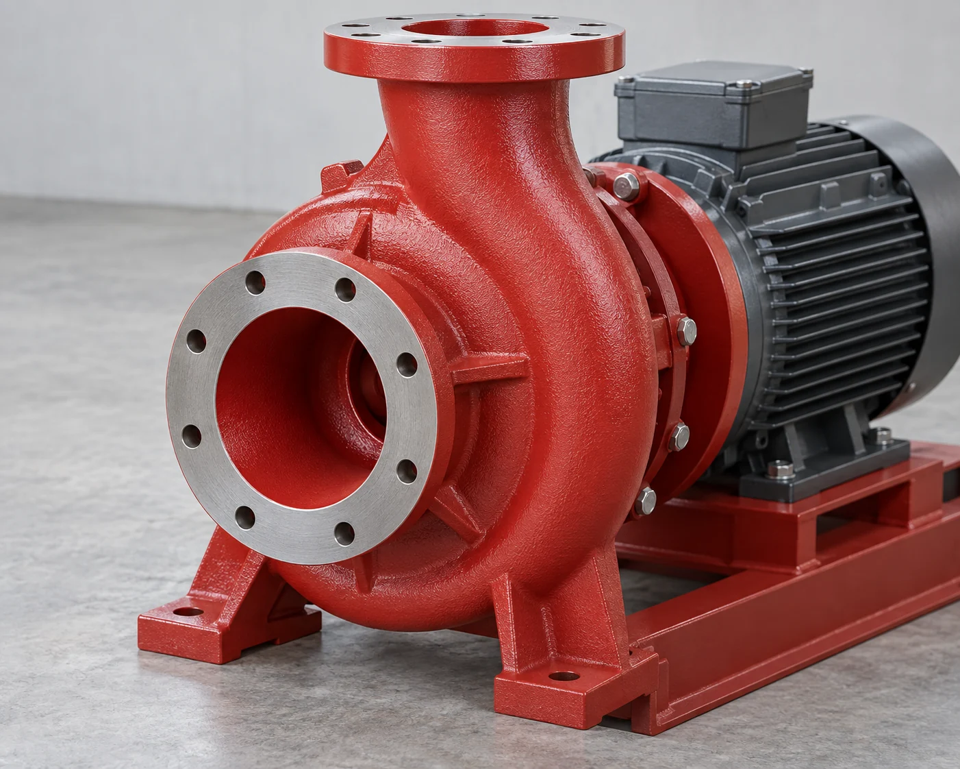
Where a spool must be removed, plan enough released clearance for the specified gasket and face arrangement, not merely enough space to extract the bolts. The required movement depends on the actual joint. Check it on the installation drawing instead of applying a universal dismantling allowance.
Keep Pipe Loads Within the Pump’s Limits
Support and align the pipe independently of the pump. Pipe forces and moments can deform the casing or disturb alignment; the selected pump’s allowable nozzle loads and installation requirements remain controlling. Do not use the flange bolts to drag a misaligned run into place.
Check the completed arrangement under the relevant operating conditions as well as cold fit-up. Thermal movement, equipment loads and any designed flexible connection belong in that assessment. A flexible connector does not automatically remove thrust or make an unsupported spool acceptable.
Example: Keep the Header Joint Closed During Pump Service
Two Acceptable Spools with Different Service Consequences
Consider a hypothetical water-pump replacement. Inspection has accepted the existing header and its flange for the new duty, but the replacement pump’s nozzle position differs. The designer has accepted two new connecting-spool arrangements for materials, rating, hydraulic behavior, supports and nozzle loads. Both fit the installation area and can be built within the planned outage. No real project performance or pricing is represented.
Arrangement A uses one continuous spool between the existing header flange and the pump. In this assumed layout, the pump service procedure requires removing that spool, opening the header joint. Arrangement B uses a retained header-side transition plus a shorter removable spool near the pump, adding one flanged break. Its accepted removal path allows the short piece to be withdrawn while the header-side joint stays assembled.

Choose the Extra Break Only When It Does Useful Work
The owner’s priority is to avoid repeatedly disturbing the existing header joint during future pump service. Choose B under these conditions. It meets that priority while accepting an additional bolted joint to assemble, inspect and maintain. A is still a valid choice if fewer joints become the priority and opening the header joint during service is acceptable.
Both service plans still require the specified isolation, draining and safe preparation of the system. Keeping a flange assembled does not authorize work on connected pressurized piping. The distinction is the joints disturbed during the planned service task, not whether the system must be made safe.
Reconsider B if the shorter spool cannot be withdrawn, the extra joint conflicts with the piping specification or the new support arrangement exceeds the pump limits. If the pump’s actual service procedure can leave the casing and connecting pipe in place, B’s added break may offer little value. Choose from that procedure and layout, not from a general preference for more removable joints.
Prepare the Joint Package Before the Outage
Specify the Complete Bolted Joint
Order each joint as a defined combination: mating flanges, gasket, fasteners and assembly requirements. ASME B16.5 covers flange ratings, dimensions and related joint requirements within its scope. ASME PCC-1 addresses bolted-joint assembly within its own scope. Neither title supplies a universal bolt torque for an unidentified retrofit connection.
Have the responsible project party set the assembly procedure for the actual materials, gasket, bolting and service. Include face inspection, alignment checks and the required examination or testing of the finished work. Keep the initial installation and any later reassembly requirements clear.
Compare the Work Done During the Outage
Compare the complete retrofit prices: survey, fabrication, loose joint materials, supports, access work, inspection, testing and reinstatement. Separate included items from buyer-supplied work and unresolved allowances. Do not claim that retaining a flange or adding a dismantling break is cheaper until those scopes are comparable.
Frequently asked questions
Can an ASME flange be bolted directly to a PN flange?
Do not infer compatibility from similar size or apparent hole alignment. Identify both standards, ratings, faces, dimensions and joint requirements. Use a properly specified matching end or engineered transition if the two connections differ.
Can the crew redrill a flange to match the new pump?
Treat drilling or machining as a design change requiring an accepted engineering and fabrication route. It is not an ordinary fit-up adjustment. Compare that route with procuring the correct flange or transition before the outage.
Will a thicker gasket correct an angular gap?
Do not use gasket thickness as a substitute for acceptable flange alignment. Resolve the geometry and loading with the project’s joint requirements; then use the specified gasket. An improvised gasket change can create a different sealing problem.
Should a weld-neck flange replace every existing slip-on?
Not automatically. The piping specification, revised service, condition and fabrication requirements decide whether the existing attachment remains acceptable. Changing attachment type does not by itself solve a nozzle-position or pipe-support problem.
Does a higher flange class increase the station’s pressure rating?
No single upgraded component establishes the rating of the complete system. The connected pipe, valves, equipment, joints and applicable design conditions still need review. Use the rating accepted for the entire affected pressure boundary.
Can the final spool be ordered before the old pump is removed?
It can be prefabricated when the relevant dimensions and conditions are sufficiently established for the accepted design. If removal may reveal unknown geometry or damage, define what can be completed beforehand and what remains a measured closure or contingency. Do not manufacture an unverified final length as a certainty.
Technical Basis and Source Scope
ASME B16.5-2025, Pipe Flanges and Flanged Fittings, official public scope: pressure-temperature ratings, materials, dimensions, bolting, gaskets and joints within the standard’s scope. ASME PCC-1, Pressure Boundary Bolted Flange Joint Assembly, public scope for the covered ring-gasket joints. Public scope descriptions checked October 19, 2026; no edition-specific assembly procedure or torque value is reproduced here.
KSB Centrifugal Pump Lexicon, Pump nozzle load and Flange type, checked October 19, 2026: nozzle forces and moments, casing/alignment effects, and facing arrangements. These references explain the interfaces; the selected pump documents and project requirements govern the actual retrofit. The two-spool example is hypothetical.
