
Define the Water-Transfer Duty Before Choosing a Pump Type
Set the Scope of “Pipeline Pump”
Here, “pipeline pump” means a pump serving industrial water pipework. It does not require an inline nozzle arrangement or refer only to long-distance oil pipelines. The selection below concerns centrifugal pumps for water-transfer duties; abrasive slurry, highly viscous fluids and unusually small metered flows need a different starting assessment.
Use Flow, Head and Hours Together
List minimum, normal and maximum flow, the required head at each condition, and the annual hours spent there. Head is energy per unit weight of liquid, expressed here in meters of water. Include the level or pressure difference between the source and destination, plus pipe, fitting and equipment losses. Pipe diameter alone cannot supply this information.
Use the system curve and the proposed pump curve to find the operating point. A different tank level, speed or open-branch arrangement can move it. Ask whether every required point lies within the selected pump’s accepted operating range, including its minimum-flow limits, rather than accepting a curve that passes through only the normal duty.
Qualify the Water and Suction Conditions
Provide water temperature, chemistry, solids and any treatment or cleaning exposure. Check the casing, impeller, shaft, seals and other wetted parts for that service. For suction, assess the lowest source level, hottest water and relevant suction-line losses. Compare available net positive suction head with the selected pump’s requirement and the margin established for the application; a barely positive difference is not proof of cavitation-free operation.
When to Consider End-Suction, Inline, Split-Case or Multistage Pumps
Shortlist by Duty and Installation
These names describe different features, so they overlap: “inline” describes the nozzle arrangement, “split-case” describes casing construction, and “multistage” describes the number of impellers in series. Treat the table as a practical shortlist of common configurations, not four mutually exclusive engineering classes.

Allow Room for the Actual Maintenance Procedure
For each candidate, compare the actual offered construction and curve. There is no universal flow threshold at which a split-case pump becomes the winner, and no pump family is automatically the most efficient. A configuration that fits the hydraulic duty can still be unsuitable if the site cannot lift its motor, remove its rotating assembly or support its connected pipework.
Swipe to view the complete table.
| Configuration | A reason to shortlist it | What can change the choice |
|---|---|---|
| End-suction | The required duty is covered by a suitable offered unit and the layout allows its motor and pump assembly | Service-removal space, shaft/seal arrangement, suction conditions and the efficiency across the required range |
| Inline | Aligned suction and discharge nozzles help fit the pipe route; an appropriate compact assembly is available | Motor lifting and removal space, approved orientation, support and nozzle-load requirements |
| Double-entry, axially split-case | Larger flow and access through the casing split make the offered design attractive | Actual curve and suction margin, lifting clearance, foundation and the selected maintenance procedure |
| Multistage | The required head is better served by multiple impellers in series than by an acceptable single-stage offer | Interstage and seal construction, service burden, pressure limits and the complete operating range |
Choose the Pump Arrangement for the Downtime the Process Can Accept
Set an Acceptable Interruption Time
A continuous-service rating does not mean a pump can run indefinitely without seal work, bearing attention or inspection. Establish how long the process can tolerate an interruption and what storage, alternate supply or standby equipment can cover that time.
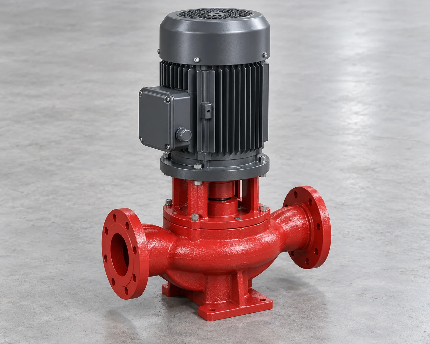
If the process needs uninterrupted transfer through a pump outage, assess a duty/standby arrangement or another accepted supply strategy. Check whether the available standby unit covers the required duty, how it starts, and how a failed unit can be isolated and drained. A shared power failure or blocked common suction can disable both pumps, so a second pump alone does not establish the required availability.
Compare Service Access, Not Just Footprint
Compare the work needed to remove the selected pump’s service parts. A small floor footprint can still require substantial overhead lifting space. Some split-case arrangements allow access to internals while lower-casing pipe connections remain in place, but the offered design and its procedure decide the actual benefit. Include lifting equipment and spares in the installed scope.
Compare Electrical Input at Every Important Operating Point
Compare the Same Electrical Boundary
For a long-running pump, a small power difference can accumulate over many hours. Obtain electrical input for each material operating condition, including motor and drive losses. Shaft power, hydraulic power and motor nameplate rating are different quantities; do not mix them in an annual electricity comparison.
Weight Power by Annual Hours
For each operating condition, multiply electrical input in kW by annual hours. Add the results to obtain kWh per year. Use the same flow, head, control method and system boundary for both offers. Include any different continuously running auxiliaries; if their consumption is unknown, leave the comparison incomplete rather than counting it as zero.
Where demand changes, compare the proposed speed-control or other operating strategy over the actual duty profile. Static head can remain even when flow falls, and efficiency changes with the operating point. Do not turn a speed reduction into a promised cube-law energy saving without checking the complete system.
Example: Annual Running Hours Decide Between Two Qualified Pumps
Make Both Offers Meet the Same Duty
Consider a hypothetical plant transferring treated water for 8,000 hours a year, with planned shutdowns during the remaining hours. Candidate A is an end-suction assembly and B is inline. Assume both meet the same water-service, suction-margin, operating-range, pressure, maintenance and continuous-duty requirements under the same speed-control strategy. Both fit the site and meet its availability requirements.
Use the Offered Power at Both Operating Points
The owner’s deciding priority is lower annual electrical consumption. The table gives invented electrical inputs for the complete pump-and-drive assemblies, including motor and drive losses. There are no differing auxiliary loads in this example. The numbers belong only to these hypothetical offers; they are not typical efficiencies or power ratings for either pump type.
Swipe to view the complete table.
| Operating condition | Annual hours | A: end-suction input | B: inline input |
|---|---|---|---|
| 200 m³/h at 40 m head | 6,000 h | 30 kW | 32 kW |
| 100 m³/h at 25 m head | 2,000 h | 12 kW | 11 kW |
Select A for This Duty Profile—and Know When B Would Win
Calculate the Annual Total
A uses (30 × 6,000) + (12 × 2,000) = 204,000 kWh per year. B uses (32 × 6,000) + (11 × 2,000) = 214,000 kWh per year. Choose A under the stated energy priority: it uses 10,000 kWh, or 10 MWh, less over the assumed operating year. This is an offer-level decision after both pumps qualify, not a general preference for end-suction pumps.

Change the Hours and the Result Can Reverse
Now change only the operating hours to 2,000 hours at the higher-flow duty and 6,000 at the lower-flow duty. A uses 132,000 kWh and B uses 130,000 kWh. B now uses 2,000 kWh less because its lower-flow advantage applies for more hours. The pump with the lower power at the normal design point is not necessarily the better choice for a different annual profile.
If the real purchase criterion is lowest lifetime cost, add comparable purchase, installation, electricity-tariff, maintenance and replacement inputs before selecting a cost winner. These energy figures alone establish no payback or lowest total cost. If neither offer has usable electrical-input data across the required range, the energy choice remains open.
Carry the Selected Duty and Configuration into the Purchase
Keep the Curve and Equipment Configuration Together
Keep the accepted flow/head cases and annual profile with the offer comparison. The selected pump, impeller configuration, speed range, motor, drive, seal and wetted materials should correspond to the performance information used in the decision. A revised motor or impeller can change the result.
Complete the scope with the installation drawing, support and allowable nozzle-load information, service clearances, controls, protection, testing and agreed spare parts. Define which performance values are guaranteed and how the purchase specification will verify them. Do not treat a family brochure’s maximum flow and maximum head as a single available operating point.
Revisit the Assumption That Changed
Before release, resolve any change in water properties, suction level, pipe resistance or expected annual operating hours. A change in hours can reverse the energy ranking; a change in the hydraulic or fluid conditions can invalidate the original qualification. Recheck the affected selection basis before substituting equipment.
Frequently asked questions
Does the best efficiency point have to match every operating condition?
No single point can match a varying duty profile. Select an acceptable operating range for the actual pump and compare efficiency across the conditions that matter. Proximity to the best efficiency point at normal duty does not excuse an unacceptable low-flow or high-flow condition.
Should I buy a larger pump now for possible future expansion?
Compare a defined future duty and a credible operating strategy with the present duty. An oversized current selection can require throttling, run outside a suitable range or consume unnecessary power. Possible future demand should not replace a usable present-day selection.
Does a variable-frequency drive always make a pump the better choice?
No. It needs a useful speed-control range within the pump, motor and system limits. For nearly constant duty, or a system with significant static head, the benefit may differ from a simple variable-flow assumption. Compare the complete proposed operating strategy and its cost.
Can the water pump be run dry briefly during startup?
Do not assume that it can. Priming, venting, seal lubrication and startup requirements depend on the selected construction and installation. Use the manufacturer’s procedure and the specified protection; a continuous-service designation is not permission to run dry.
Is a close-coupled inline pump automatically supported by the pipe?
No. Follow the specific unit’s support and installation requirements and check allowable pipe loads. Aligned nozzles describe the connection arrangement, not permission to hang any pump assembly from unsupported pipework.
Can two smaller pumps share the duty instead of using one large pump?
They may, but establish the combined pump and system behavior, the operating sequence and each unit’s acceptable range. Parallel flow is not automatically twice the single-pump flow at the original system operating point. Also check how the remaining unit performs when one is unavailable.
Technical Basis and Source Scope
U.S. Department of Energy, Improving Pumping System Performance: A Sourcebook for Industry, Second Edition, May 2006, DOE/GO-102006-2079: fluid properties, p. 7; installation and maintenance, pp. 31–34; Appendix C, Pumping Systems Tip Sheet #3, pp. 107–108, for efficiency across the operating range. Used for system principles, not current product ratings or a universal suction-margin rule.
KSB Centrifugal Pump Lexicon, “Operating Point,” “System Characteristic Curve,” “Multistage Pump,” and “Pipeline Pump”; KSB in-line pump family explanation and Omega product-family description; checked October 19, 2026. These identify mechanisms and construction options, including split-case water-service arrangements. They do not establish an efficiency winner, a product recommendation or the numerical values in the hypothetical example.

