
What changes in the open flow path?
A gate valve moves a closure member across the pipe opening. In a full-bore design, opening the valve lifts that member out of the flow stream. A butterfly valve rotates a disc through 90 degrees; at full opening the disc lies approximately parallel to the pipe and remains inside the flow path. This geometric difference explains why the hydraulic comparison matters.
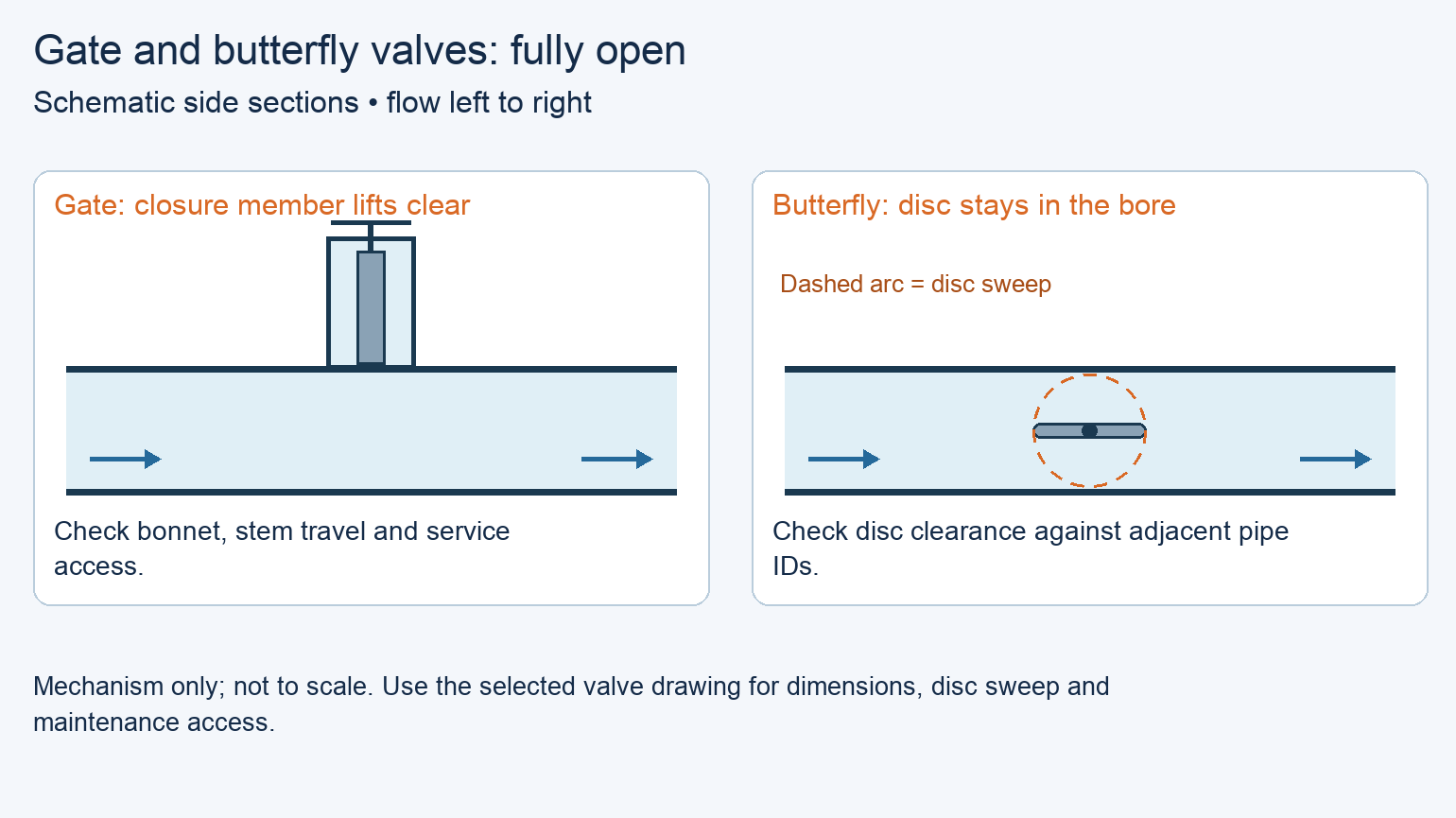
Full bore still needs a hydraulic check
Neither geometry establishes a pressure-loss value by itself. Gate bore details and butterfly disc, hub and shaft geometry affect the result. Use the flow coefficient or loss curve for the actual size and configuration, rather than a generic percentage advantage.
Which valve fits the duty and available space?
This comparison concerns isolation in liquid industrial-water lines. Before ranking either type, match the specified maximum operating pressure and temperature, surge conditions, water chemistry and solids, required shutoff leakage, end connections and actuator duty. A missing seat-compatibility statement or pressure rating leaves that candidate unresolved; it does not make the other valve type inherently better.
Compare the assembly, including access
Once both candidates satisfy those requirements, compare the complete assemblies. A gate bonnet accommodates the lifted gate; a rising stem also needs travel space above the operator. A nonrising stem removes that external stem travel, but the bonnet and parts-removal envelope remain. A butterfly assembly can occupy less space, although its gearbox and disc sweep still need room.
Check the butterfly disc beyond the flange face
For butterfly valves, check the disc throughout its rotation against the actual pipe and flange inside diameters, including liners, and any nearby check-valve disc. Bray’s 2-Cx manual, section 9.1.1, specifically calls for checking adjacent-pipe clearance. A matching nominal size and bolt pattern cannot establish this clearance.
Swipe to view the complete table.
| When both candidates qualify | Gate valve consideration | Butterfly valve consideration | What should decide |
|---|---|---|---|
| The line carries flow for long periods | A full-bore design removes the gate from the stream | The open disc and shaft remain in the stream | Compare actual pressure loss at the operating flow |
| The valve bay is crowded | Check bonnet, stem travel and removal space | Check body length, gearbox and disc sweep | Prefer the accepted assembly that preserves useful access |
| The valve is operated remotely | Confirm actuator thrust or torque and travel time | Confirm torque through the stroke and closure timing | Use the approved operating sequence and transient limits |
| Seat service must fit the outage plan | Check bonnet access and the specified repair procedure | Check seat-side access and whether field repair is permitted | Compare the selected models’ service tasks and access |
Compare pressure loss at the actual flow
The flow coefficient Cv expresses the water flow in US gallons per minute associated with a 1 psi pressure drop across a valve. For the water calculation used here, pressure drop in psi is ΔP = SG × (Q / Cv)², where Q is flow in US gpm and SG is liquid specific gravity relative to water. The coefficient must match the valve’s operating position.
Use a specific size and disc design
AVK’s published fully open DN600 tables give the values below. The gate table covers resilient- and metal-seated full-bore gate valves; the butterfly table is specifically for the Series 756 plate disc. These are manufacturer hydraulic data, not proof that two offered valves have matching pressure ratings, materials or end connections.
At the same flow, the higher Cv produces the lower calculated valve loss. Compare the absolute difference with the allocated valve-loss budget. Keep losses from reducers, adjoining fittings and the rest of the line separate; a valve Cv comparison does not calculate the complete system head.
Swipe to view the complete table.
| Published DN600 fully open data | Cv, US gpm at 1 psi | Source |
|---|---|---|
| AVK full-bore gate valves | 127,735 | Flow Parameters for Gate Valves, rev. AH, April 3, 2025, p. 1 |
| AVK Series 756 plate-disc butterfly valve | 40,166 | Flow Parameters for Butterfly Valves, rev. AH, October 15, 2025, p. 1 |
A DN600 choice: space first or pressure loss first
Hypothetical design exercise. Consider a DN600 water main carrying 10,000 US gpm, with SG = 1.0 and the isolation valve fully open. Assume two candidate assemblies have already passed the same pressure, temperature, materials, shutoff, connection, disc-clearance and transient checks. Use the published Cv values above only as hydraulic inputs; the exercise does not establish that the catalog valves meet these assumed approvals.
Flow, pressure-loss allowance and installation bay
Assume the project allows 0.10 psi of steady-state pressure drop across this valve and provides a 1.50 m axial installation bay. The gate valve plus removable spool reserves 1.20 m; the butterfly valve plus removable spool reserves 0.75 m. Both have accepted operator and service access. These space allowances are hypothetical; use the offered assembly dimensions for a project comparison.
The gate calculation is (10,000 / 127,735)² = 0.00613 psi. The butterfly calculation is (10,000 / 40,166)² = 0.06198 psi. Both fall below the assumed 0.10 psi limit. The butterfly arrangement uses 0.45 m less axial space, while its calculated valve pressure loss is about 0.05586 psi higher.
Space savings versus lower valve loss
If preserving space is the first priority, select the butterfly arrangement in this exercise. It leaves 0.75 m of the bay unreserved, compared with 0.30 m for the gate arrangement, and still meets the assumed valve-loss limit. The gate’s lower loss does not meet the stated space objective as well.
If the first priority is the lowest steady-state valve loss and either arrangement fits, select the gate arrangement. It gives the lower calculated loss at the same flow. The difference is only about 0.056 psi here, so this result alone does not justify a higher purchase price or establish an energy-cost payback.
Higher flow or revised valve dimensions
Recalculate if flow or the selected Cv changes; at unchanged Cv, doubling flow makes this calculated loss four times larger. Reopen the layout comparison if actual spool, operator or removal dimensions change. If either candidate fails a pressure, material, clearance or closure requirement, resolve that failure before using the two-way preference above.
Set closure behavior and maintenance access
A quarter-turn butterfly disc does not mean a quarter turn of every handwheel. Val-Matic’s BFV-OM4-10 manual describes a geared operator with multi-turn input and instructs slow opening and closing to prevent water hammer. Specify the required travel time and closure behavior with the system transient assessment. Neither “gate” nor “butterfly” by itself establishes a safe closing time.
Separate isolation from continuous regulation
Conventional gate valves serve fully open or fully closed isolation, rather than sustained throttling. If the duty includes flow regulation, select a valve and actuator rated for that service and obtain the opening-dependent flow data and allowable operating limits. Do not assume an isolation butterfly valve is suitable merely because its disc can stop partway.
Check how the seat can actually be serviced
Repairability depends on the selected construction. Val-Matic’s cited Series 2000 manual describes seat adjustment and replacement with suitable access. Bray’s 2-Cx manual states that its valve is not intended for field repair. Compare the actual maintenance procedures, necessary isolation, lifting access and spare parts before assigning either type a lower maintenance cost.
Put the choice on the valve schedule
For each isolation position, record the selected type and size, water service, pressure and temperature limits, required shutoff performance, wetted and seat materials, end connections, operator and closure requirements. Include the accepted Cv or loss curve and the drawing showing operating and service clearances. These details define the scope of an industrial valve order.
Match the mating connection and quote scope
For flanged assemblies, identify the applicable flange standard and class, facing, drilling, mating bore and gasket arrangement. Keep these details aligned with the pipe-flange schedule. Compare quotations for the same valve, actuator, coatings, tests, spares and delivery scope; without that scope and actual prices, neither valve type has a demonstrated installed-cost advantage.
Frequently asked questions
Is there a diameter above which a butterfly valve is always better?
No universal diameter cutoff settles the choice. Increasing size makes the complete valve, operator and removal space more consequential, but actual pressure loss, pressure rating and available models still determine the comparison. Use the dimensions and hydraulic data for the offered size.
Can a nonrising-stem gate valve solve a low-ceiling problem?
It avoids the external upward stem travel of a rising-stem design. It still needs space for the bonnet, operator and the removal path specified by its maintenance procedure. Check the service envelope as well as the closed-valve height.
Can a butterfly valve replace a gate valve in the same pipe run?
Sometimes, but it is a layout change. Compare face-to-face length, flange compatibility, pipe bore and lining, disc sweep, support arrangement and operator access. Confirm the replacement’s pressure, material and closure requirements before changing the spool.
Does an EPDM seat automatically suit industrial water?
No. “Industrial water” can include treatment chemicals, contaminants and temperature conditions that matter to the elastomer. Obtain compatibility confirmation for the specified seat compound and the actual service, including any cleaning exposure, rather than approving it from the EPDM label alone.
Which valve type causes less water hammer?
The type name does not decide it. Flow conditions and how flow changes during the closing stroke matter. A geared butterfly valve may close slowly, while a powered valve of either type needs an approved closure sequence. Use the system transient assessment to set that sequence.
Does lower valve pressure loss justify a higher purchase price?
Only a calculation with the actual operating duty can answer that. Convert the verified loss difference into pumping-energy effects using flow, operating hours and pump efficiency, then compare energy cost with the installed-price and maintenance differences. A Cv ratio alone is not a payback calculation.
Technical Basis and Source Scope
U.S. Department of Energy, DOE Fundamentals Handbook, Mechanical Science, Volume 2 of 2, DOE-HDBK-1018/2-93, Rev. 0 (January 1993), Module ME-04, pp. 4–5 and 14 (stem designs), pp. 8–9 (gate valves), and pp. 31–32 (butterfly valves). Archived training material used for basic mechanisms, not current project compliance.
Val-Matic, 30-inch and Larger Series 2000 Butterfly Valve With LSA Actuator and External Stops: Operation, Maintenance and Installation Manual, BFV-OM4-10, pp. 1–3, 6 and 11. No issue date identified in the opened copy. Bray, 2-Cx PTFE-Lined Butterfly Valves: Installation, Operation and Maintenance Manual, copyright 2023, section 9.1.1, p. 12; section 10.1.6, p. 19; section 13, p. 23. Installation and repair statements apply to the identified constructions.
AVK Group A/S, Flow Parameters for Gate Valves: Resilient and Metal Seated, Full Bore, rev. AH, April 3, 2025, p. 1, DN600 row; and Flow Parameters for Butterfly Valves: Series 756 / Plate Disc, printed rev. AH, October 15, 2025, p. 1, DN600 row. Definitions appear on p. 2 of each document. The 10,000 US gpm duty, acceptance limits, layout dimensions and candidate approvals in the worked exercise are hypothetical.
