Start with the Pile Shape and Toe Condition
H-Piles and Soil Displacement
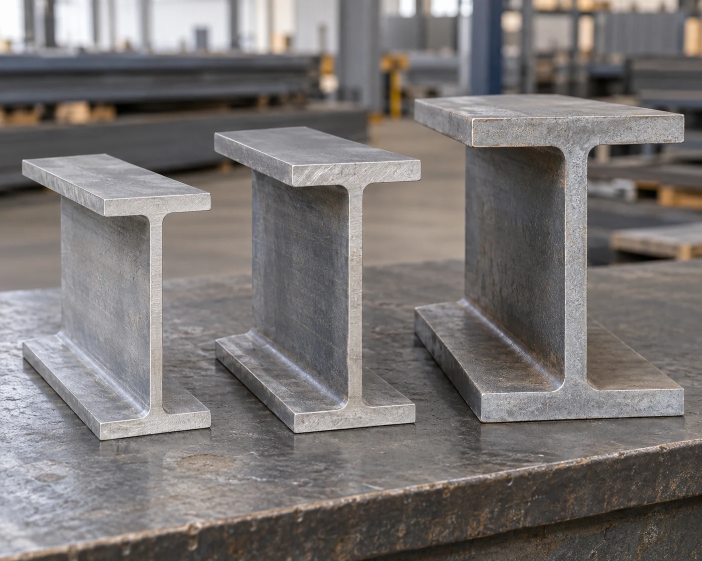
H-piles are open steel sections with a web between two flanges. Their relatively small displaced volume can help when driving through dense layers. They can still deflect or suffer damage at obstructions. A low-displacement description is not permission to drive through any buried material.

Open-Ended and Closed-Ended Pipe
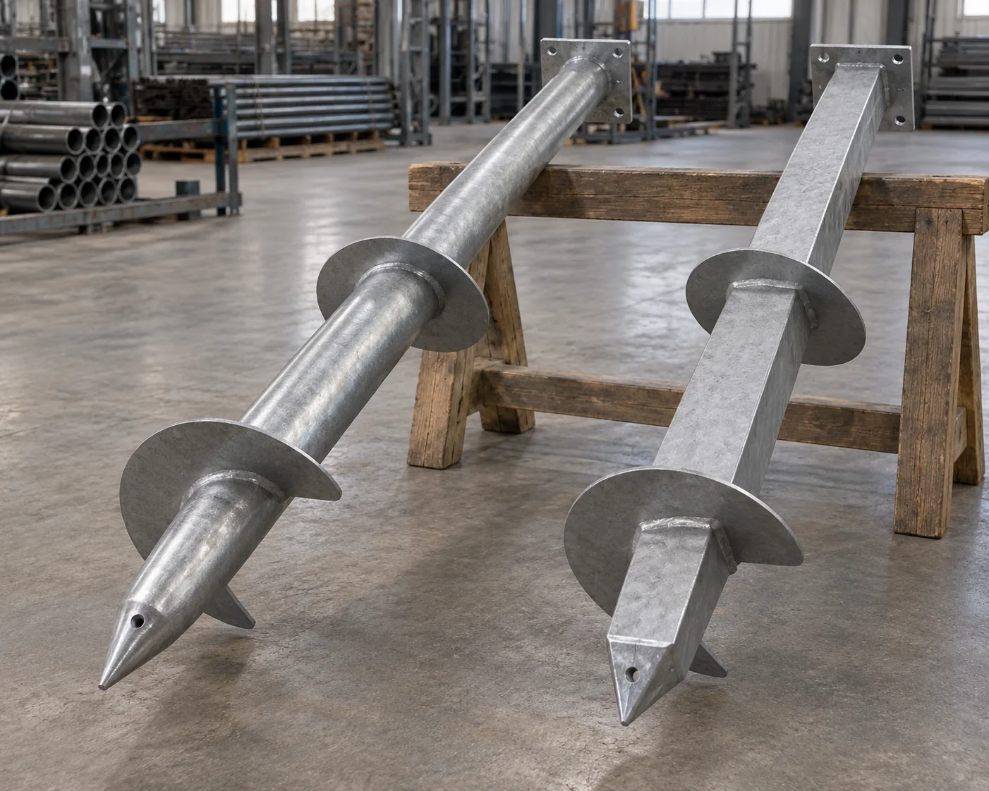
A closed-ended pipe pushes soil aside across its toe area. An open-ended pipe allows soil to enter, but a soil plug may develop and change driving resistance and load transfer. H-sections can also plug between their flanges. The words “pipe pile” therefore leave an important installation condition unanswered.
Specify the proposed pipe toe, wall and any shoe or closure detail before comparing it with an H-pile. These are driven foundations; helical piles and shallow footings are different alternatives, not variations of this comparison.
Compare Bending Direction and the Pile Head
Round Symmetry and H-Pile Orientation
An ideal uniform circular pipe has the same section bending stiffness about every centroidal axis in its cross-section. An H-pile has distinct strong and weak bending axes. Its installed orientation therefore matters. This is a difference in steel-section geometry; the surrounding soil, exposed height and head restraint still control how the installed foundation moves.
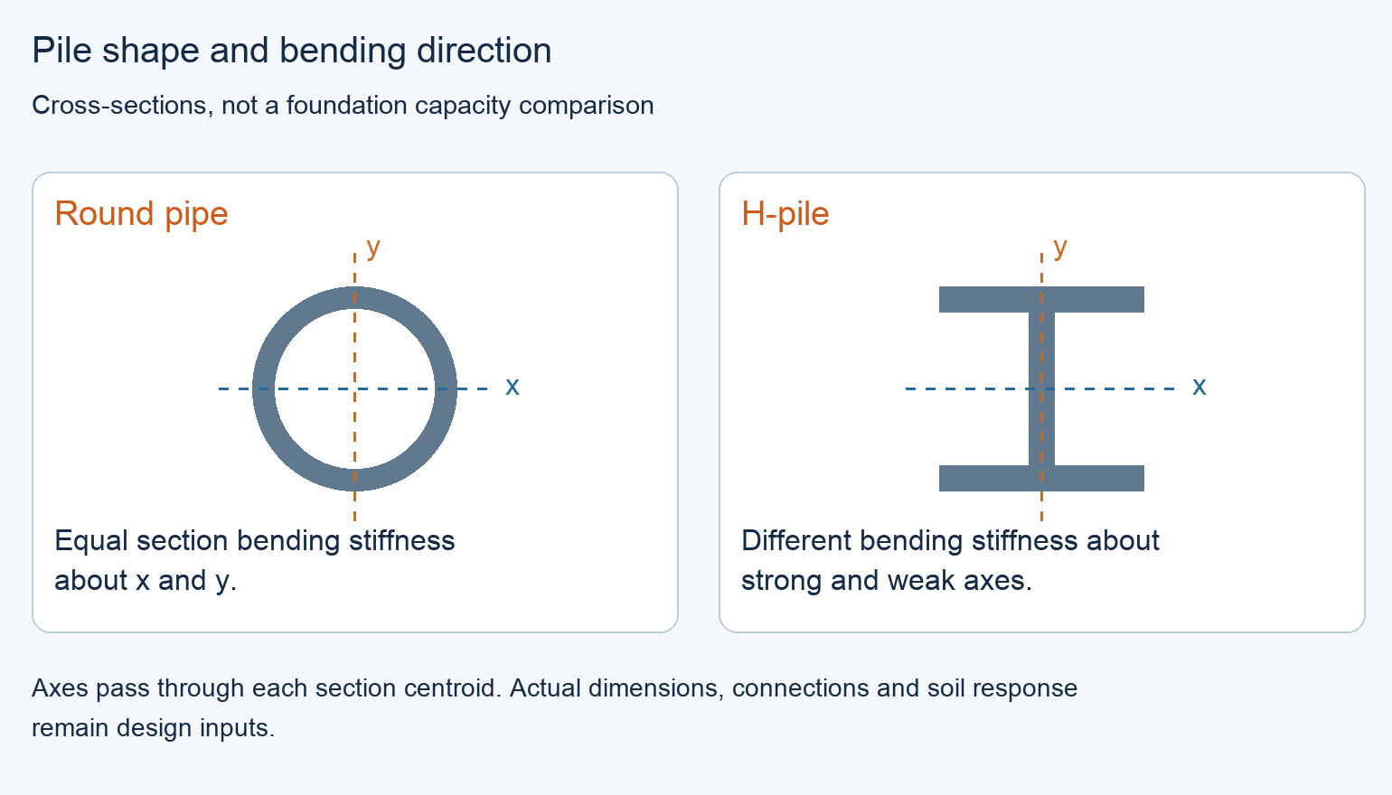
Use that distinction when comparing supports with loads from different horizontal directions. Round pipe avoids a strong-axis versus weak-axis orientation choice for the shaft. H-piles can place their stronger axis where it is useful, but both directions must work. Neither observation proves that a particular pipe is stiffer than a particular H-section.
The Connection Can Change the Preference
An H-section provides flat web and flange faces that may suit a designed bolted bracket. A pipe may use a designed cap, sleeve or saddle. Compare the actual load-transfer detail, tool access, tolerances and site work. A convenient-looking surface does not authorize drilling holes or adding welds.
What Must the Site Investigation Resolve?
Loads and Movement
Use the same support reactions and movement limits for both offers. Solar foundations need the applicable wind uplift and lateral actions as well as compression. Industrial supports may have different reaction combinations, equipment requirements or tolerable movement. UMass research on elevated fixed solar arrays illustrates why uplift deserves explicit attention; it does not supply a design capacity for a different site or tracker.
Ground Conditions and Installation
Map the soil layers, groundwater, fill and obstructions to the proposed pile locations. Add corrosion exposure, frost and erosion where relevant. DOE winter-weather guidance emphasizes site-specific frost and soil conditions; a pile depth copied from another solar project is not a substitute.
The installation assessment must match the proposed section, toe, hammer and soil profile. FHWA GEC 15 discusses drivability and pre-production testing because both steel H-piles and pipe piles can be damaged in hard driving. Define the required field observations and any compression, uplift or lateral tests before production, with acceptance criteria for the actual project.
How to Choose When Both Piles Work
Match the Priority to a Real Difference
After both foundation schemes meet the project requirements, rank the differences that remain. The following priorities are alternatives, not a scorecard: the owner’s controlling task determines which advantage matters.
Swipe to view the complete table.
| Project priority | Option to examine first | Condition that keeps the comparison valid |
|---|---|---|
| Limit soil displacement during driving | H-pile or a suitable open-ended pipe | Compare actual plugging and installation behavior; do not group open and closed pipe together |
| Avoid shaft strong-axis/weak-axis setting across changing support directions | Round pipe | Head connections and soil behavior still need their own directional checks |
| Use a flat-face pile-head bracket | H-pile | Approved holes, bracket and fasteners fit the specified section and reactions |
| Manage variable pile lengths | Either | Compare feasible splices, inspection and handling; both types can be extended |
| Find the lowest completed foundation cost | Either complete offer | Include installation, connections, testing and agreed treatment of ground-related changes |
A Choice for a Solar Site with Differently Oriented Rows
Two Qualified Foundation Schemes
Consider a hypothetical fixed solar array whose layout contains several row directions. The geotechnical and structural teams have accepted both proposed foundations for the same site zones, loads, movement limits and durability requirements. Trial installation is satisfactory for each. The H-pile drawings specify the shaft orientation for each row group. The round-pipe scheme has a uniform circular shaft and approved adjustable head connections. Both setting-out plans are feasible; neither has a missing approval.
Why Pipe Wins This Particular Choice
The owner’s stated preference is to reduce the number of shaft-orientation instructions across the row groups. Select the pipe scheme for that preference: rotating a uniform circular shaft does not interchange strong and weak section axes. Pile position, verticality and the head’s orientation still need control. The H-pile scheme remains a valid alternative with its orientation marks and checks.
If all rows use a common orientation, or the pipe-head design fixes the shaft orientation anyway, this advantage may disappear. An H-pile offer with a useful flat-face connection or a better complete price could then be preferred. A new hard layer encountered during installation is a separate issue: reassess the affected foundation and driving plan rather than treating the original selection as approval to continue.
Compare the Installed Scope Before Ordering
A Complete Pile Schedule
Use the project pile schedule: section and grade, pipe toe condition where applicable, required lengths, pile-head details, corrosion provisions and identification by site zone. Include shoes, closure plates, splices and concrete fill only where the selected design requires them. Pipe piles do not universally require concrete filling.
Material Price Is Only Part of the Comparison
Compare delivered material plus the remaining driving, head-connection, testing and inspection work. Separate included items from separately priced work and owner costs. Agree how length changes, rejected piles and approved obstruction remedies will be measured and priced. An unknown item is not zero, and a lower price per ton does not establish a lower completed cost.
Keep the accepted section and installation criteria linked to the purchased material. Changing a pipe wall, H-section, toe detail or driving method can alter both installation and performance. Treat the change as an engineering revision before substituting it in the field.
Frequently asked questions
Does refusal prove that the pile has enough capacity?
No. Refusal before the required penetration can indicate an obstruction or another installation problem. Compare the driving record with the specified acceptance criteria and obtain the responsible engineer’s assessment. A high blow count alone does not close every compression, uplift or lateral requirement.
Can a general H-beam replace the specified H-pile?
Not simply because the outside dimensions look similar. Compare the exact section designation, web and flange geometry, material grade and project requirements. Some structural sections can be used as piles through project-specific design, but a substitution needs that assessment before purchase. A general beam catalog is not evidence that the specified pile is being supplied.
Can a compression test replace an uplift or lateral test?
It does not directly establish those different responses. Use the project’s analysis and testing plan to decide which tests are needed. A successful compression result is not, by itself, a measured uplift resistance or lateral-deflection result.
Is a closed-ended pipe the same as a concrete-filled pipe?
No. Closed-ended describes the toe; concrete-filled describes the interior. State both separately. The design determines whether fill, reinforcement, internal inspection or another completion task is required.
Can one pile specification cover every soil zone?
It can if the design and verification support that choice for all relevant zones. Otherwise use a zone-specific schedule and identification system. Do not transfer the result from an easy-driving test location to a materially different part of the site.
Does specifying galvanized steel settle the corrosion question?
No. The durability design must consider the actual soil, water exposure, required life and installation damage, together with any coating or section allowance. A finish name alone does not establish the remaining steel thickness throughout service.
Technical Basis and Source Scope
FHWA, Design and Construction of Driven Pile Foundations, Volume I, FHWA-NHI-16-009, July 2016, Tables 6-2–6-3, Sections 6.3–6.4 and 8.2.2: pile forms, plugging, splices and section properties. Transportation guidance is used for these mechanisms, not as a solar-site design approval.
FHWA, Acceptance Procedures for Structural Foundations of Transportation Structures, GEC 15, April 18, 2022, Sections 4.1.2 and 4.4–4.5: drivability, testing and acceptance of driven foundations.
Alan Lutenegger, University of Massachusetts, Foundations for Elevated Ground Mount Solar Panel Photovoltaic (PV) Systems, August 1, 2019, pages 2–3: research scope and uplift considerations for elevated fixed arrays. DOE FEMP, Solar Photovoltaic Hardening for Resilience – Winter Weather, “Frost Heave,” checked October 15, 2026: site-specific frost and soil conditions.