
Choose a Solar Carport Layout That Preserves Fleet Access
Vehicle Envelopes Come Before Module Count
Lay out the vehicles before maximizing the panel area. Include the largest vehicle assigned to each bay, mirrors, open doors or tailgates, charging-port location and the swept path used to enter and leave. Check the lowest point of the whole canopy assembly, including braces, gutters and attached equipment. The column layout must work with foundations, existing utilities and protected pedestrian routes.
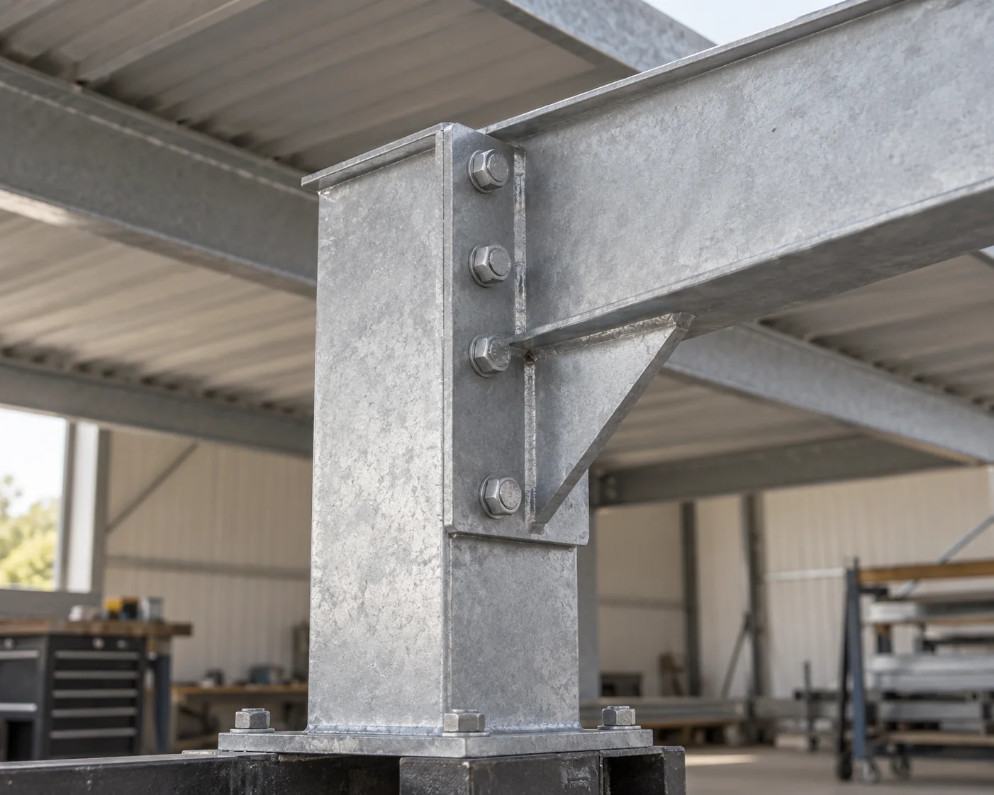
Double-Row, Single-Row and Pull-Through Canopies
A double-row canopy can serve opposing bays from a shared central strip when that strip is outside the vehicles’ usable envelopes. A single-row canopy can suit a boundary row or a site that cannot accommodate central supports. A pull-through arrangement may be preferable for vehicles that should avoid reversing or need uninterrupted movement. These are layout starting points; none has a universal span, clearance or foundation advantage.
Put charging equipment where its cables reach the actual vehicle ports without crossing a traffic aisle or required walking route. A column is not automatically an acceptable charger mounting point: check the equipment, mounting loads, impact protection and service access in the coordinated design.
Swipe to view the complete table.
| Depot condition | Configuration to evaluate | Main condition to resolve |
|---|---|---|
| Opposing parked rows with a usable central service strip | Double-row canopy with shared central charging distribution | Column, charger and cable locations must preserve each bay |
| Boundary parking or no acceptable central support strip | Single-row canopy with charging on the usable service side | Vehicle doors, port reach and edge clearance |
| Long vehicles or operations that should avoid reversing | Pull-through layout with protected charging equipment | Turning paths, cable handling and unobstructed departures |
| Fleet growth is expected but timing is uncertain | Modular canopy and planned electrical expansion routes | Reserve physical space without assuming spare electrical capacity |
Match Charging Power to the Parking Window
Energy, Dwell Time and Vehicle Acceptance
List when each vehicle returns, when it leaves and the energy it needs before departure. Distinguish energy delivered to the battery from energy drawn at the charger input; the latter includes charging losses. Use the vehicle’s actual charging acceptance and the charging equipment’s capabilities. Charger nameplate power does not guarantee that a vehicle accepts that power throughout the session.
Long, predictable dwell periods can allow lower-power charging spread over several hours. Short turnaround periods may require higher power or a different operating plan. Managed charging allocates power within the site’s available capacity while prioritizing departures. The site limit must account for other electrical loads, rather than treating the transformer rating as unused capacity.
Charging Connections Are Different from Simultaneous Demand
Treat the number of connectors and simultaneous power as separate decisions. Sharing fewer connectors can require staff to move vehicles or cables during the night. Providing a connector at each assigned bay can avoid that task while a controller limits total power. The preferred arrangement depends on actual staffing, vehicle compatibility and the required departure schedule.
Decide What Solar and Storage Must Do
Solar Production Must Be Compared by Time
Compare the charging load with a time-based PV generation estimate and the depot’s other loads. A fleet that is away all day and charges at night has limited direct overlap with solar production. Daytime PV may serve other depot loads or approved exports, but an annual energy balance does not prove that nighttime charging is supplied directly by the canopy.
Give Storage a Specific Job
Grid-connected charging is a practical starting point when reliable grid capacity meets the departure schedule. Consider a battery when shifting solar energy, managing a defined demand peak or meeting an outage requirement has sufficient value. Size and evaluate that task using power, usable energy, losses, controls and the tariff; adding a battery is not automatically the best configuration.
If charging during a grid outage is required, define which vehicles must receive how much energy and by when. Ordinary grid-connected PV is not a promise of backup charging. The project needs an explicitly designed and commissioned islanding or backup arrangement, including the applicable electrical approvals.
Example: A Solar Carport for 12 Overnight Vans
Check the Charging Schedule
Consider a hypothetical depot with 12 vans parked from 6 p.m. to 6 a.m. Each needs 30 kWh measured at the charging input, including charging losses. The site reserves 48 kW of continuous capacity for charging after other loads. Assume every van and port can sustain an allocated 3.6 kW until its required energy is delivered. No solar generation is credited during the charging window.
Twelve connections at 3.6 kW draw 43.2 kW, below the assumed 48 kW limit. Each van receives its 30 kWh input in 30 ÷ 3.6 = 8.33 hours, or 8 hours 20 minutes. Starting at 6 p.m. gives an illustrative completion time of 2:20 a.m. The fleet receives 360 kWh in total. Real scheduling must still reflect actual acceptance, interruptions and any changing site load.
Choose Between Qualified Canopy Layouts
The site already has two opposing rows of six bays and a service corridor between them. Assume two complete canopy proposals meet the same structural, drainage, vehicle-clearance and electrical requirements. Proposal A is a double-row canopy with protected charging distribution in the central corridor. Proposal B uses separate single-row canopies and longer distribution routes around the outside of the parking area. Both provide 12 connections and the same managed charging schedule.
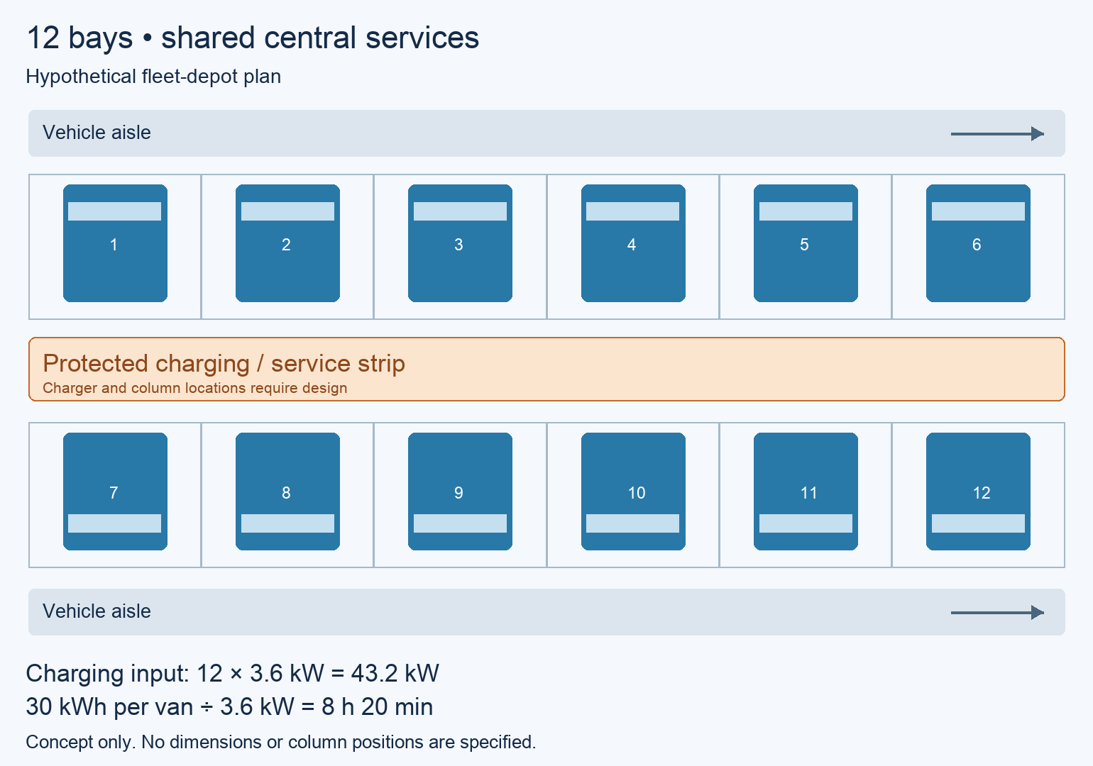
Choose A for this depot: it uses the existing parking and service arrangement while keeping both outer aisles clear. Specify grid-connected PV and managed charging, with future electrical routes planned during construction. Do not add a battery merely because the charging occurs at night; its energy-shifting or backup value still needs a separate evaluation. This selects the configuration, not a lowest-price supplier.
If a larger replacement van cannot use the central-strip layout, revisit the canopy geometry. If arrivals shift later or a second shift needs the vans sooner, rerun the charging schedule. If a new building load removes the reserved electrical capacity, the original arithmetic no longer qualifies the charging plan. Those changes can alter the configuration even when the number of vehicles stays at 12.
Plan Drainage and Expansion with the Canopy
Keep Water and Snow Away from Charging Areas
A PV module array does not automatically form a watertight roof. Specify the required deck or weather cover, gutters and discharge path. Keep runoff and seasonal ice or snow issues away from charging positions and walking routes. The drainage design must suit the local conditions and stormwater arrangement.

Prepare Expansion Routes and Define Supply Boundaries
Show where future chargers, conduits, distribution equipment and any proposed storage would go before paving and foundations are fixed. Spare conduits provide a route; they do not create electrical capacity. Reserve only the future structural loads that the canopy designer has actually included.
Compare offers with the same boundary: structural canopy and foundations, PV equipment, weather cover and drainage, chargers, electrical distribution, controls and commissioning. These items may come from different contractors. A complete configuration identifies the interfaces without assuming that a carport-frame quotation includes a functioning charging station.
Frequently asked questions
Does every fleet bay need a dedicated charger?
Every bay does not necessarily need a separate power cabinet, but the connection plan must match the parking schedule. Shared or multi-port equipment may work. If a vehicle must be moved or a cable swapped, include that staffing task rather than assuming it will happen unattended.
Should the solar array be rated equal to the chargers’ total power?
No fixed equality is required. PV size depends on usable canopy area, generation conditions, electrical limits and the value of its output. Charger power depends on vehicle energy needs and available time. Compare their time profiles and the site connection separately.
Can a central row of columns be used for any fleet?
Only if the complete column, foundation, brace and equipment envelope fits the actual parking and movement plan. Vehicle length, doors, tailgates and charging ports can change that fit. Check the largest vehicle intended for the bays, including planned replacements.
Do night-charging fleets always need batteries?
No. A suitable grid connection may meet the charging schedule. Storage becomes a candidate when a quantified shifting, demand-management or backup task justifies it. A daytime solar surplus alone does not establish battery size or economic value.
What should happen if the charging controller loses communication?
Specify the fallback behavior with the electrical and fleet teams before procurement. It must respect the site’s electrical limits and the required operating plan. Test loss of communications and recovery during commissioning; a cloud dashboard is not proof of a safe or useful fallback.
Can charging be added after the canopy is installed?
Yes, when routes, equipment locations and structural and electrical capacity allow it. Planning conduits and interfaces during the initial work can reduce later disruption. Recheck available power and the new fleet schedule before adding charging loads.
Technical Basis and Source Scope
U.S. Department of Energy, Smart Charge Management Implementation for Federal Fleets, “Data Requirements,” “Action Items/Implementation Pathway” and “Commission the System,” checked October 19, 2026: vehicle schedules, site capacity and control objectives.
U.S. Department of Energy, Managed and Bidirectional Charging, “Managed EV Charging” and the discussion of future EVSE conduit provision; Life Cycle of Photovoltaic Systems: Install and Commission a Photovoltaic System, “Carport PV Systems,” checked October 19, 2026. Used for integrated planning, drainage and utility considerations. The twelve-van layout and charging values are explicit teaching assumptions, not DOE recommendations or a METDAX project result.