
Start With the Equipment Reactions and Permitted Movement
Loads at Each Attachment
An equipment weight is not a column reaction schedule. The frame designer needs the forces and moments at each attachment, their directions and heights, and the operating, startup, shutdown and maintenance conditions that must be considered. Include connected piping or conveyor forces where they enter the frame. Dividing total weight by the number of legs can miss unequal reactions and eccentric loads.
Use the same column height, bracing arrangement, base restraint and equipment layout for both proposals, or identify how a changed arrangement affects the design. The reaction schedule should identify units, reference axes and whether loads are service-level or factored. The project engineer then uses the applicable design basis and load combinations; individual maximum reactions are not automatically simultaneous.
Movement, Alignment and Vibration
Strength and movement answer different questions. Specify the permitted displacement and rotation at the equipment attachments, together with alignment and access requirements. For vibrating or rotating equipment, obtain the manufacturer’s operating speeds, excitation information and acceptance criteria for a dynamic assessment of the complete support. A larger column or a passing static check does not, by itself, demonstrate acceptable vibration.
How the Two Column Shapes Change the Design
Bending Direction and Torsion
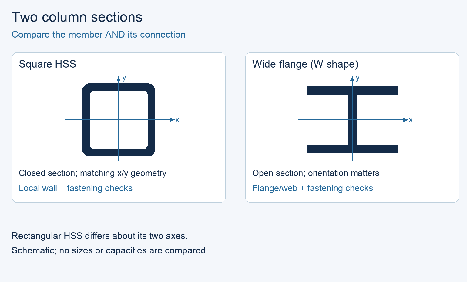
A W-shape has two flanges joined by a web. Its bending properties differ about its two principal axes, so show the installed orientation on the drawings. Square HSS has matching geometric properties about those axes; rectangular HSS does not. Neither symmetry nor a higher steel grade establishes the resistance of the actual column. Height, restraint, wall or flange slenderness, combined forces and connections still matter.
A closed HSS cross-section offers useful torsional stiffness. A W-shape subjected to torque can require attention to twisting, warping and the restraints that transfer that torque. Compare the actual designs rather than assuming an open section cannot carry torsion or that every HSS is stronger. Where feasible, moving an eccentric attachment or changing the load path may be more useful than increasing the column size.
The Connection Can Govern the Choice
The connection can reverse the apparent advantage. Loads entering an HSS face act on the local wall as well as on the whole member. The designer must address the relevant wall and connection failure modes, including local wall deformation or yielding and fastener pull-out where applicable. A thicker wall, an engineered reinforcing detail or a different connection can change the result. A stronger weld alone does not prove the tube wall is adequate.
An open W-shape often gives better access to the opposite side of a flange or web for bolting, welding and inspection. That access must still be checked against stiffeners, adjacent members, guards and the tool envelope. HSS can also use field-bolted connections, but the design needs a workable means of fastening to a closed member. Do not assume that an ordinary nut will remain reachable inside a finished tube.
Which Column Should You Evaluate First?
Match the Shape to the Support Task
First require the proposed member, frame and connections to meet the complete load and movement brief. Then compare maintenance access, fabrication, finish and availability. The following conditions identify a starting point; they do not select a section size.
If the load schedule or a decisive connection check is missing, hold that proposal rather than assigning the unknown item a passing result. If both complete designs meet the requirements, neither shape deserves a default preference: compare their actual fabricated and installed offers.
Swipe to view the complete table.
| Support condition | First option to evaluate | What decides |
|---|---|---|
| Significant torsion or bending in more than one direction | HSS, alongside any practical load-path change | Actual member response and a connection that transfers all required forces |
| Frequent removal of side-mounted equipment or brackets | Wide-flange, if its exposed faces suit the attachment | Tool clearance, fastener access and the complete flange/web connection |
| Bending mainly in one plane; connections suit that plane | Wide-flange in the appropriate orientation | Major- and minor-axis checks, restraint and required movement limits |
| Compact closed profile needed for the equipment layout | HSS | Outside dimensions plus space for plates, fasteners and maintenance |
| Rotating equipment, cyclic loading or an incomplete reaction schedule | Neither proposal can be accepted from shape alone | Dynamic/fatigue inputs as applicable and the missing project checks |

When Both Column Designs Pass the Engineering Checks
Compare the Installed Connection and Maintenance Access
Assume both complete member-and-connection designs meet the same forces, movement and environment. An HSS option can offer a closed profile and several flat attachment faces, but mid-height connections still need a workable fastening arrangement for the inaccessible interior. A W-shape exposes the flange/web region, often allowing conventional bolt heads and nuts to be reached from opposite sides, subject to the actual stiffeners and surrounding equipment.
For frequent bracket removal, compare the actual wrench insertion path, bolt extraction space and replacement-fastener arrangements after guards and piping are installed. If both engineered options work but the HSS uses one-sided fasteners while the W detail uses the plant’s standard spare bolt system, the latter can better fit that maintenance preference. If the equipment layout favors a closed profile and the HSS connection remains accessible, HSS can be the preferred arrangement.
Neither family is universally cheaper or more capable; compare their actual fabricated offers after the design checks. The example below shows why an adequate column still needs a verified bracket connection.
Connection Qualification for an Indoor Equipment Support
Project Conditions and the Torque Component
Consider a hypothetical indoor support frame with fixed attachment positions and a maintenance requirement to remove a side bracket using ordinary tools. Both proposals are assumed to have passed the same preliminary member-strength and frame-movement checks. Proposal A uses square HSS; Proposal B uses W-shaped columns.
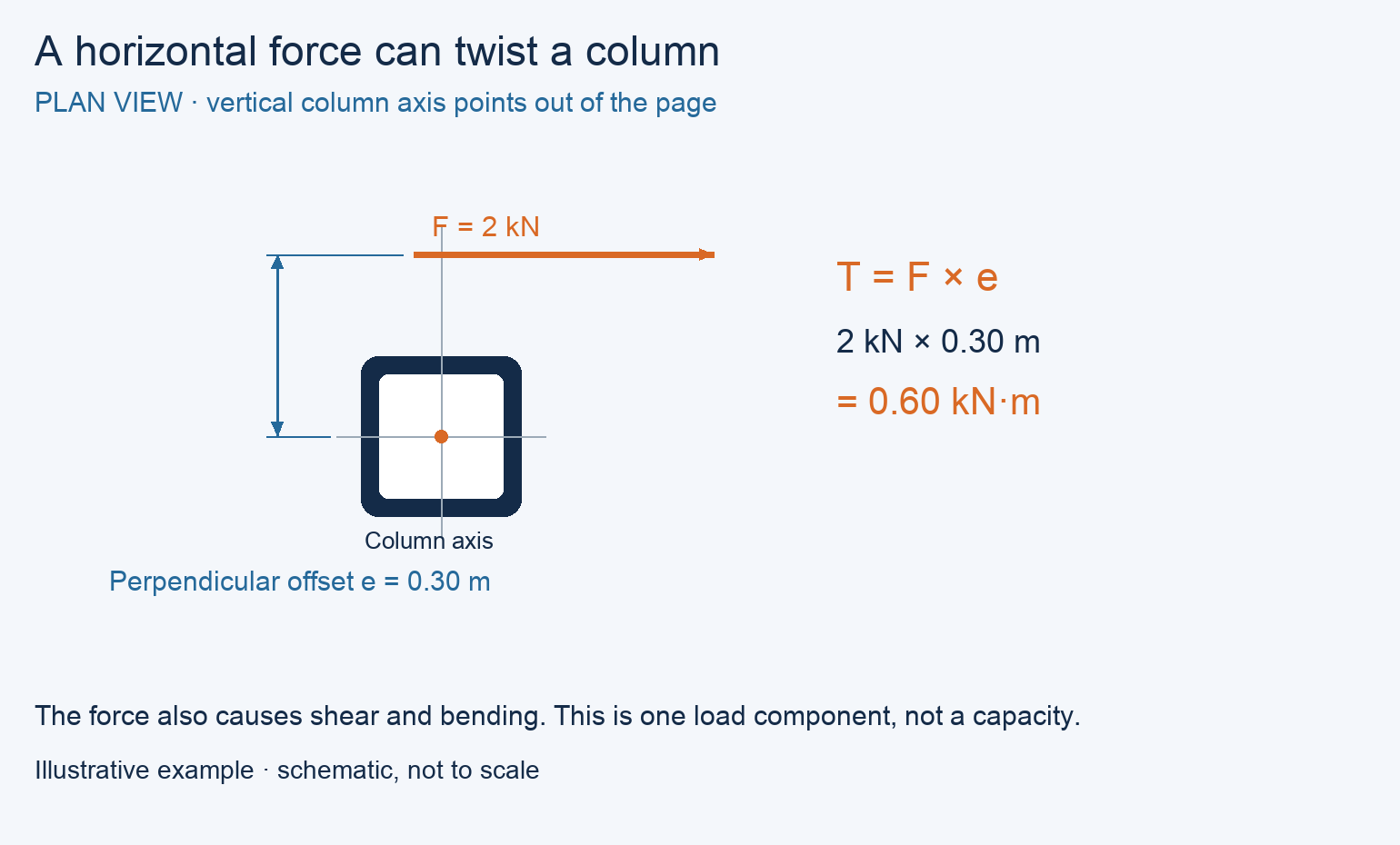
At one attachment, a horizontal force of 2 kN has a line of action offset 0.30 m from the column’s vertical centerline in plan. Its torque about the vertical column axis is T = F × e = 2 × 0.30 = 0.60 kN·m. The force also produces lateral shear and bending because it acts above the base. This torque calculation is only one component of the load assessment, and it does not determine a safe column size.
An eccentric vertical gravity load is a different case: it produces bending about horizontal axes, rather than torque about the column’s vertical axis. Name the force direction and the axis of the moment before treating an eccentric load as column torsion.
Swipe to view the complete table.
| Item | Proposal A: square HSS | Proposal B: W-shaped columns |
|---|---|---|
| Preliminary member strength and frame movement | Assumed adequate for the stated brief | Assumed adequate for the same brief |
| Side-bracket load transfer | Local wall and fastening assessment missing | Complete force/moment transfer assumed verified |
| Bracket removal and tool access | Not demonstrated | Assumed to meet the maintenance requirement |
| Current decision | Hold as an alternate pending the missing checks | Preferred for further design and matched quotation |
| Fabrication release | Not approved | Not yet approved; remaining project items still open |
The Preferred Proposal and What Would Change It
In this example, prefer Proposal B for the next design and quotation stage. Its connection assessment covers the required force and moment transfer, and the tool-access check meets the maintenance brief. Hold Proposal A’s bracket detail until the HSS wall and fastening arrangement are verified. HSS torsional stiffness does not compensate for that missing connection result.
The choice would reopen if A gained an adequate, accessible bracket detail, or if a changed load path removed B’s access advantage. There is no price winner without matched quotations. Final drawings, finish, base/anchor interfaces and any remaining project checks are still required before fabrication release.
Compare Fabrication, Maintenance and Finish
Use the Complete Fabricated Cost
Price the accepted connection details along with the columns. Include plates, stiffeners, slots or access openings, weld preparation, fasteners, inspection, coating, installation and freight on a common scope. A lighter member or lower price per pound does not establish the lower completed cost. Items included in a quoted package are counted once; excluded or unpriced work remains visible.
For HSS, check whether the detail can be welded and inspected from the available side and how field connections will be installed. For W-shapes, check access around the web, flanges and any stiffeners. Obtain the fabricator’s actual process and availability proposal for the specified grade and geometry. Do not prescribe more cutting or a more demanding weld type merely because it looks stronger on a sketch.
Access and Corrosion Protection
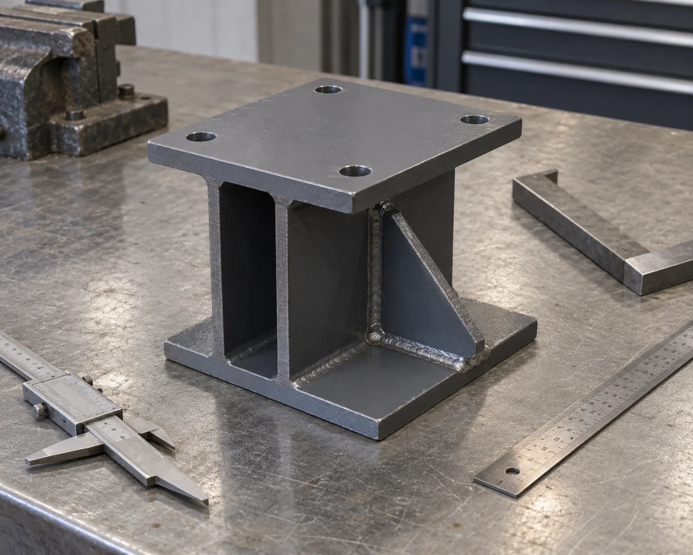
A maintenance plan should show how brackets, guards and fasteners are reached after equipment and piping are installed. HSS has a less accessible interior; the design must address moisture entry, end closures and any required drainage. Open sections expose more surfaces for inspection, but plates and stiffeners can also create hard-to-reach areas. Neither shape is inherently corrosion-proof.
If the completed fabrication will be hot-dip galvanized, its enclosed spaces need an agreed venting and drainage layout before fabrication. Locations depend on the member geometry, internal paths and dipping orientation. Square or rectangular assemblies should not simply copy a circular tube detail. Have the project designer and galvanizer resolve the openings; this article supplies no universal hole size.
What to Specify Before Ordering or Substituting
Keep the Member and Connection Schedule Together
The accepted material list should identify section designation or outside dimensions and wall thickness, material standard and grade, length, quantity and installed orientation. Pair it with the connection drawing revision, plate and fastener requirements, weld/inspection scope and finish. The associated design record should retain the reaction schedule, restraint assumptions and equipment movement criteria.
A proposed HSS-to-W or W-to-HSS substitution needs more than an equal weight, depth or axial-compression table entry. The project engineer must address combined loading, stiffness, connection force transfer, member fit and base/anchor interfaces. For dynamic or cyclic service, preserve the applicable equipment and fatigue criteria. Purchase the reviewed member and connection schedule after the affected design changes have been accepted.
Frequently asked questions
Can I bolt equipment to an HSS column without reaching inside it?
Yes, an engineered one-sided fastening arrangement can make that possible. The exact fastener system, plate geometry, tube wall and required shear or tension transfer must be checked. It is not equivalent to drilling a hole and assuming any ordinary bolt will work.
Can a through-bolt replace a welded bracket connection?
Only after the complete detail is designed. A bolt passing through both walls of a hollow member can distort the walls when tightened, and its bearing and load-transfer behavior differs from a conventional bolted plate joint. Sleeves or other engineered reinforcement may be appropriate; the approved detail controls installation.
Does a square HSS column have the same capacity in every direction?
Its geometric properties match about its two principal axes, but the installed frame may have different restraints, attachments and load effects in those directions. Connections and combined loading can govern. Symmetry is not a capacity certificate, and rectangular HSS has different properties about its principal axes.
Should I fill HSS columns with concrete for equipment support?
Treat that as a separate composite design option. Filling a tube changes weight, load transfer, connections and construction requirements; it does not automatically cure an inadequate side bracket or unacceptable vibration. Compare an engineered composite proposal with the original complete design.
Is a structural tube interchangeable with a similar-looking pipe?
No automatic substitution is justified by appearance or outside size. The specified product standard, grade, wall, geometric properties and connection details must match the accepted design, or the project engineer must review the alternative. Retain the material identification and certificates for the supplied member.
Can I drill new equipment holes after the support frame is delivered?
Have the project engineer review the hole location, diameter, edge distances and changed attachment loads first. New holes can affect the member or connection, while drilling also disrupts an existing coating. Record the accepted drawing revision and required finish repair before modifying the frame.
Technical Basis and Source Scope
Connection basis: Steel Tube Institute, Welding of HSS, March/April 2012, opening discussion; Review of AISC Design Guide 24 second edition, July 2024, chapters 2 and 4, local-wall/fastener behavior. Old equations are not prescribed as current code requirements.
MIT Structural Mechanics: torsion of thin closed sections, Fall 2002 — Explains closed-section torsion mechanics; it does not select an equipment-support column or connection.