What Do the Rails Actually Do?
Two Routes from Module to Roof
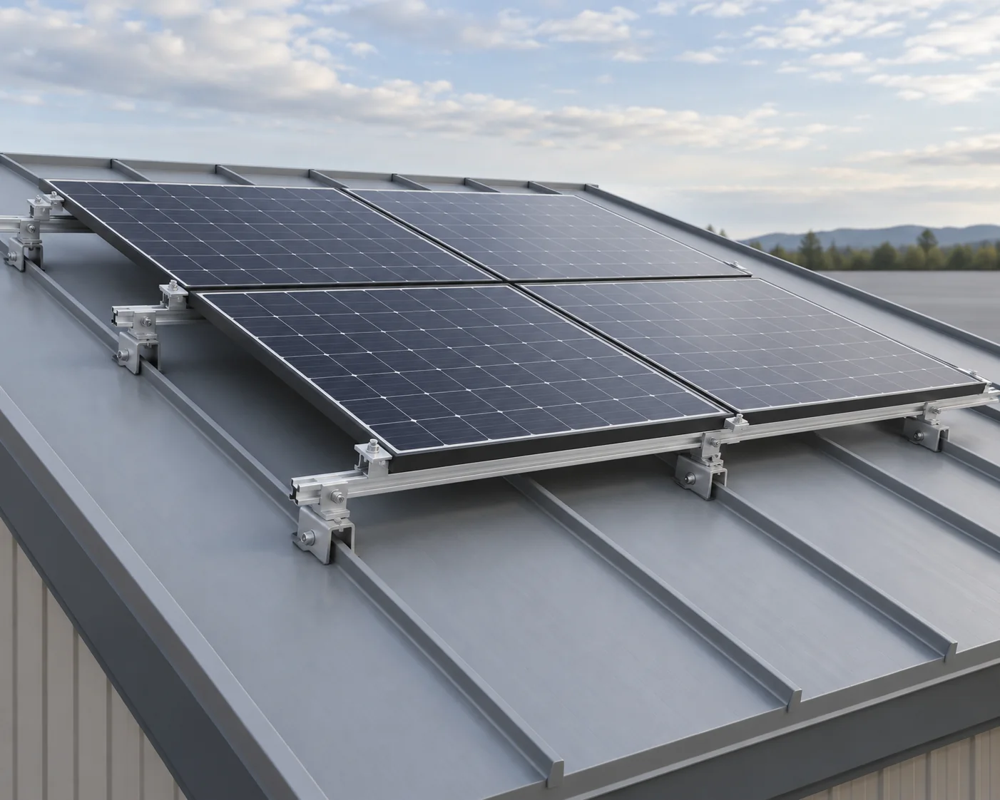
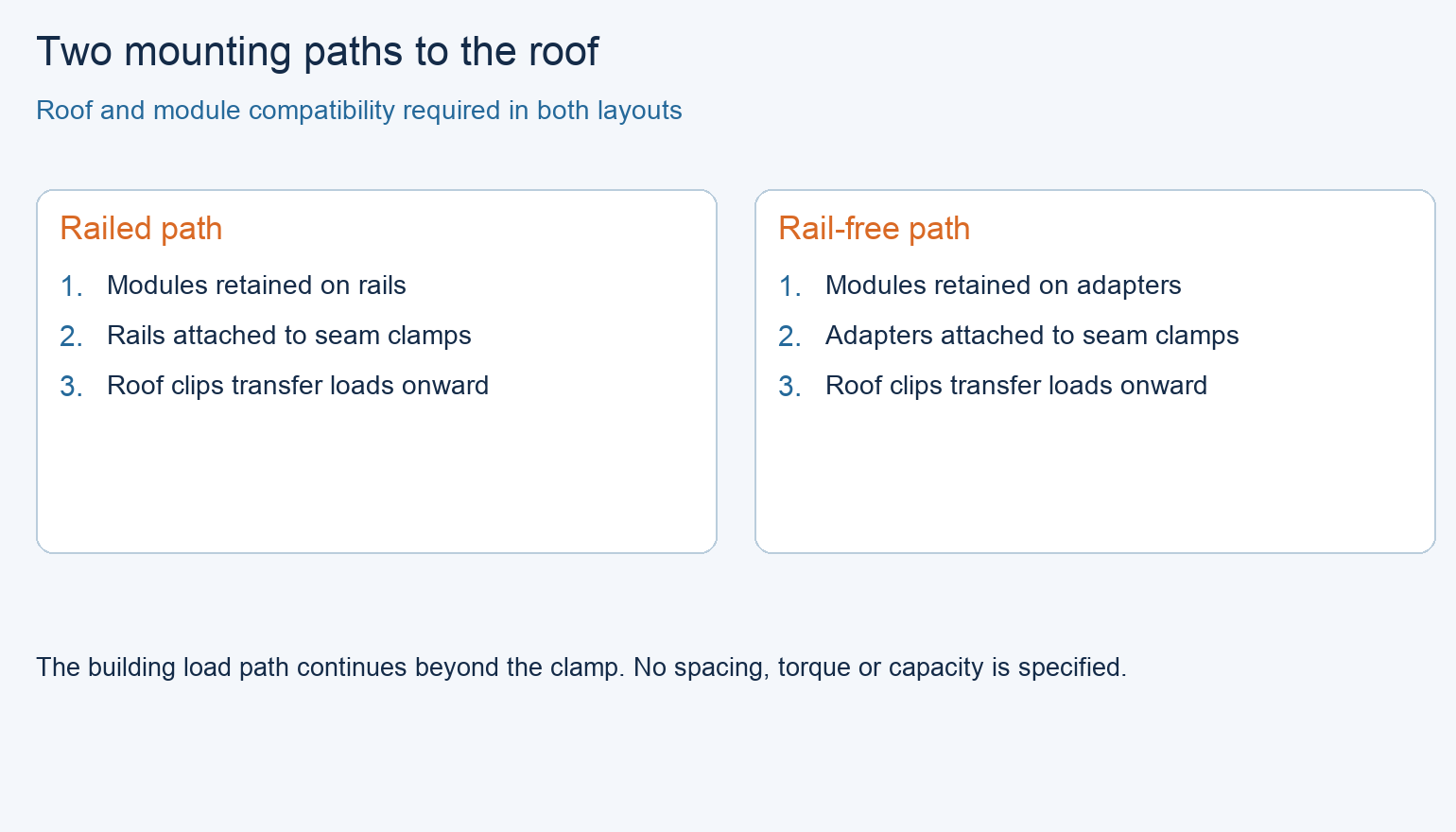
In the systems compared here, both mounting paths attach to standing seams with external seam clamps. A railed system supports the modules on rails connected to those clamps. A rail-free system connects module-retention hardware to the seam clamps without the continuous support rails. Small adapters, support disks or other specified parts can still be required.
Layout Flexibility and the Material List
Rails can separate the module-support positions from the roof-seam positions within the accepted design, and provide locations for compatible cable or electrical-equipment supports. A direct-attachment layout instead has to align its permitted module-support positions with the available attachment arrangement. Neither system allows arbitrary clamping anywhere on a module frame.
Removing rails removes those items from the material list, but it does not prove a lighter or cheaper complete system. Compare all required clamps, adapters, bonding and wire-management parts, as well as their actual delivery units.
Make Sure the Roof and Modules Support the Layout
Roof Identity and Load Transfer
Identify the actual panel profile, material, thickness, seam geometry and concealed roof-clip arrangement. Check roof condition and the building’s ability to accept the array. The proposed clamp must fit that seam, and the complete layout must carry the site loads through panels, clips and supporting structure. Do not substitute a generic “standing seam” description for the installed roof identity.

FEMA’s April 2018 USVI Recovery Advisory 5 warns that rails can overstress concealed roof clips and emphasizes preserving thermal movement at seam attachments. Its recommendation for external seam-clamp attachment is a reason to examine the complete roof load path, not approval for every rail-free arrangement. A railed proposal must demonstrate that its load transfer is suitable for the actual roof.
Module Support and Certification Scope
For the modules, check model, frame geometry, permitted clamping zones, orientation, support arrangement and loading limits. Compare those positions with the surveyed seams and the proposed adapters or rails. Rail-free mounting is viable only when the exact combination works; rails also need a supported module and mounting configuration.
Review the actual certification and installation records for each proposed combination. UL’s September–October 2022 Question Corner explains that a UL 2703 listing can cover particular functions, such as mechanical loading, bonding or a fire classification, with specified modules and conditions. A listed clamp is not automatic evidence that every roof, module, bonding path and fire assembly is covered.
Which Differences Matter After Both Systems Qualify?
Useful Flexibility or Simpler Material Handling
Once both layouts satisfy the roof, module, structural and electrical requirements, compare how they serve the project. A railed layout can be preferable where its permitted adjustment range or accessory locations solve a real layout task. A rail-free layout can be preferable where avoiding long rail units makes roof delivery and staging easier.
The Work That Remains
Check what the installation crew actually has to move, assemble and inspect. Rail-free systems still need alignment, attachment completion and cable support. Railed systems add rail positioning and any specified splices, but those rails may be useful to the equipment layout. Compare the actual work plans rather than a universal minutes-per-module saving.
Swipe to view the complete table.
| Project priority | Option to evaluate first | Decisive condition |
|---|---|---|
| Adjustable module-support or accessory positions | Railed layout | Accepted rail, support, movement and module positions provide the needed flexibility |
| Avoiding long mounting-stock delivery and staging | Rail-free layout | Direct attachment works for the exact combination; all other required parts are included |
| Existing roof clips or thermal movement not established | Hold the affected layout | Complete roof load path and permitted attachment locations are resolved |
| Electrical equipment, drainage or service access constrained | Both complete layouts | Compatible equipment supports, cables and maintenance routes fit |
| Both practical; no overriding physical preference | Compare full installed offers | Same array function, completion scope and project-specific prices |
A Complete Choice on One Industrial Roof
Same Approved Functions, Different Delivery Units
Assume the same standing-seam industrial roof, module model, array area and required access routes. Both layouts are accepted for the project’s loads, roof-clip arrangement, module clamping, thermal movement, bonding and applicable fire requirements. Both installation plans are feasible. The railed offer uses specified 4.00 m rail delivery units; the rail-free offer has no continuous rails and its loose mounting pieces are no longer than 0.50 m. The PV modules and their delivery plan are common to both. These are hypothetical proposal inputs, not standard product dimensions.
The Preference and Its Reversal
The owner wants to minimize long mounting-stock movement and temporary storage on a busy roof. Choose the rail-free layout for that priority: it removes the 4.00 m rail-handling task while retaining the accepted direct-attachment arrangement. The railed option remains suitable and installable. This is a handling preference, not proof of a labor percentage or a lower installed price.
Reopen the choice if the railed offer supplies an accepted shorter-unit and splice arrangement that removes the handling disadvantage, or if its useful accessory/layout flexibility outweighs that task. A changed roof or module model is different: it reopens the affected technical compatibility for both offers before either can be treated as qualified.
Price and Release the Complete Mounting Scope
Equivalent Supply and Installation
Make both offers include the roof attachments, module retention, specified bonding, wire management, equipment supports and required service clearances. Identify rail splices and movement provisions where applicable. State which engineering, roof investigation, installation and inspection tasks are included and which are separately priced.

Add the remaining lifting, staging and roof-protection work from each installation plan. An included item is not added again; an unpriced item is not zero. Carry any owner-required roof-warranty review into the scope. Without comparable complete prices, keep the physical preference separate from the commercial award.
A Maintainable Released Layout
Release matching drawings and component schedules for the accepted roof and module combination. Retain the applicable installation instructions and inspection requirements. Arrange accessible cable and equipment supports and a workable module-removal procedure. Rails or adapters should not obstruct drains or the agreed maintenance routes.
Frequently asked questions
Does rail-free mounting mean the roof is never penetrated?
The seam-clamp mounting path can avoid penetrating attachments at those points. Cable entries, electrical equipment or other roof work may still need separate details. Review the whole project before calling it penetration-free, and obtain the roof system’s acceptance of the actual work.
Must rail-free modules always be installed in landscape orientation?
Do not make that a universal rule. The permitted orientation follows the exact module, seam spacing, support hardware and loading configuration. Use the applicable installation records and accepted layout; a landscape example does not authorize portrait installation or exclude every portrait system.
Does a UL 2703 mark cover all bonding and fire requirements?
Check the individual listing and its specified functions, components and installation conditions. Mechanical loading, bonding and fire classification are distinct scopes. Do not infer a complete grounding path to the roof or a roof fire classification merely from a marked clamp.
Can a replacement module use the old clamps and layout?
Check the replacement model’s frame, permitted clamping zones, support and loading requirements, plus the mounting system’s applicable records. Similar power output or outside size is insufficient. Reassess any changed combination before assuming the existing hardware remains suitable.
Can rails or clamps be shortened or moved to avoid a roof obstruction?
Only through an accepted revised layout and the applicable product instructions. Cutting a rail, relocating an attachment or changing a splice can alter spans, load transfer, movement and bonding. Keep drains, skylights and required access clear through the design rather than an improvised site change.
What needs attention when one module is removed for service?
Use the system’s removal procedure, including any temporary bonding measures and the retention of neighboring modules where they share hardware. Provide a cable-isolation and access plan appropriate to the work. A removable module is not evidence that removal leaves every mechanical and electrical path intact.
Technical Basis and Source Scope
Pacific Northwest National Laboratory, Building America Solution Center, Roof Anchor System for Solar Panels, checked October 14, 2026: compatibility, product instructions and roof-access considerations. Apply the actual project requirements; residential examples are not industrial-roof approval.
FEMA, USVI Recovery Advisory 5, Rooftop Solar Panel Attachment: Design, Installation, and Maintenance, April 2018, pages 7–8: complete attachment load path, concealed clips and thermal movement. The cited edition is historical guidance, not a claim to have checked current code calculations.
UL Solutions Question Corner, September–October 2022, IAEI Magazine, pages 14–15: UL 2703 listing functions and specified combinations. S-5! PVKIT 2.0 Solar Manual, version 022519, Sections 1.4 and 2.4: one manufacturer’s direct-attachment and removal/bonding example. These product references explain scope limits; they do not establish a current listing or compatibility for METDAX components.