Start with the Equipment Feet and the Skid Supports
Rails and Crossmembers Follow the Support Layout
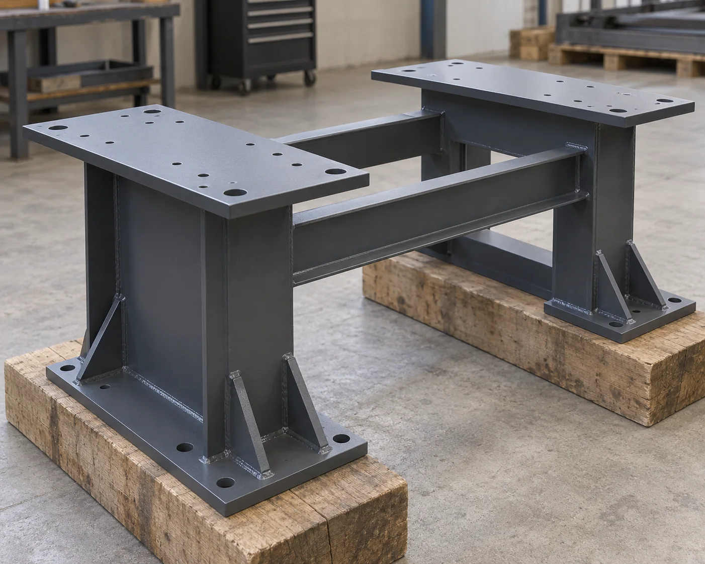
Draw where the equipment bears on the base and where the base bears on its foundation, isolators or support points. The main rails carry load between those supports; crossmembers distribute it and connect the rails. A mounting pad may need a local plate or stiffener even when the rail itself is adequate. Equipment weight divided by four is not a substitute for the actual reactions at four feet.
Use the equipment manufacturer’s operating, startup, shutdown and maintenance loads and its permitted movement at the mounts. Identify loads from piping and other attachments, plus separate lifting and transport arrangements where relevant. The final section designation comes from those design cases, the spans and the connections—not from a rule such as “use channel below this machine weight.”
Static Strength Does Not Set Vibration Performance
For rotating or reciprocating machinery, evaluate the assembled machine, base and supports dynamically. A static strength check does not establish vibration performance. Resonance depends on excitation and the system’s natural frequencies; changing the rail, crossmembers or support condition can change the response. Use the equipment’s acceptance criteria rather than a universal clearance from operating speed.
Where Channels, Wide-Flange Beams and HSS Fit Best
Channels for Accessible Connections
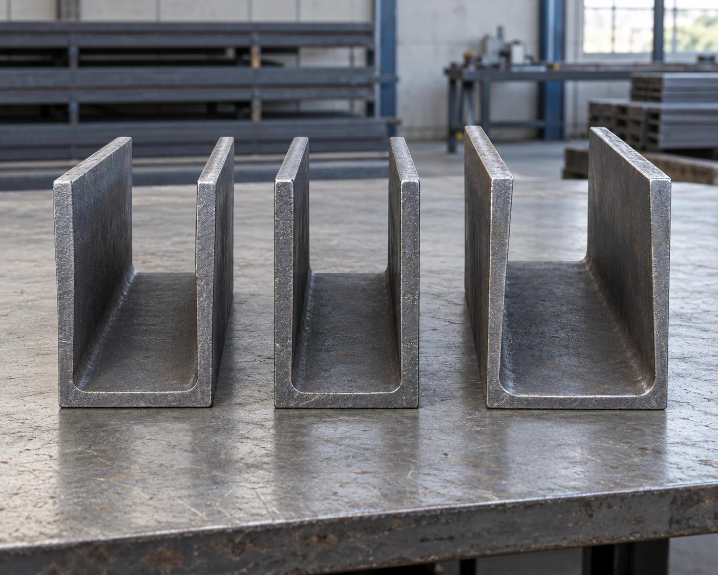
An open channel leaves one side accessible for fastening and inspection. That can make removable crossmembers or brackets practical. Its asymmetric section also makes the load position important: a force away from the shear center can twist the channel. Show the installed orientation and restraints; do not treat a channel as a smaller interchangeable I-beam.
Wide-Flange Rails for Directional Bending
A wide-flange beam offers distinct major- and minor-axis bending properties and accessible web and flange surfaces. It is a useful candidate for a main rail when its depth and orientation suit the required bending stiffness. Local equipment loads still need a path through the flange and web, and the designer must consider lateral restraint and twisting.
Rectangular HSS for a Closed Frame
Rectangular hollow structural sections (HSS) provide a closed perimeter that can be useful for torsional stiffness. Their flat faces can suit compact fabricated frames, but those faces also receive local mounting and connection loads. A closed profile does not make a thin wall an adequate bolt seat. Compare the actual sizes, wall thicknesses, restraints and attachments rather than ranking shape names alone.
Use angles for suitable secondary brackets or bracing, and built-up plate members when the geometry or mounting needs justify custom fabrication. These are designed parts of the base, not automatic substitutes for the main rails. Combining section families is reasonable when each member has a clear job.
Swipe to view the complete table.
| Main requirement | Section to evaluate first | Detail that can change the choice |
|---|---|---|
| Frequent access to removable fasteners | Channel or another open section | Wrench clearance, load eccentricity and restraints |
| Main-rail bending stiffness with available depth | Wide-flange beam | Installed axis, local load introduction and lateral restraint |
| Twisting demand or a compact closed rail | Rectangular HSS | Wall behavior and access at each attachment |
| Unusual mounting geometry or integrated pockets | Built-up plate section | Weld access, distortion control and inspection scope |
Choose the Mounting Detail Before Ordering the Section
Service Access After Equipment Installation
Place the equipment foot, pad, fastener and rail on the same detail. Check whether a tool can reach the fastener after the equipment, guards and piping are installed. A connection that can be assembled on an empty bench may be inaccessible during maintenance.
HSS Fasteners Need a Designed Load Path
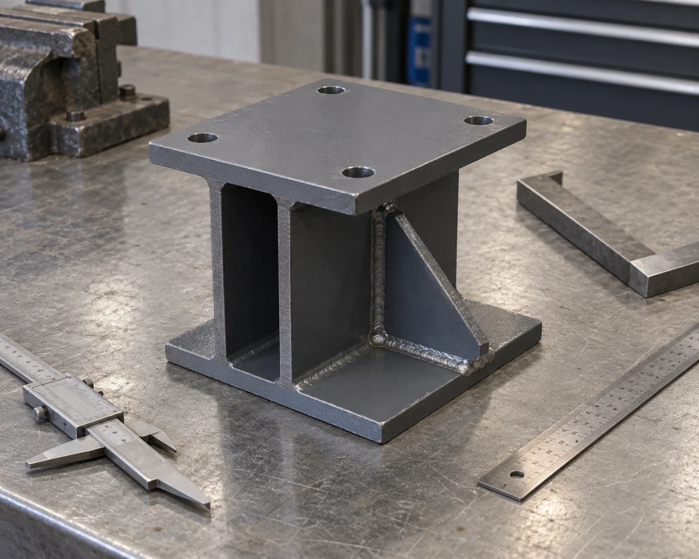
For HSS, practical options can include designed external connection plates, suitable one-sided fasteners or other engineered details. Cutting an access hole changes the member; running a bolt through both walls can distort them if the detail is unsuitable. Neither is a general fix to be improvised after fabrication. Steel Tube Institute’s bolting guidance discusses both access and local wall behavior.
Mounting Pads Are Finished Interfaces
For alignment-sensitive machinery, define the finished mounting surfaces and their relationship to each other. Decide how welding, any required machining, coating and inspection fit into the manufacturing sequence. The rolled section’s nominal dimensions alone do not define the flatness or coplanarity of a finished machine mounting surface.
Example: Choosing a Base with Removable Crossmembers
Compare Two Complete, Qualified Bases
Consider a hypothetical indoor pump-and-motor package. It needs two main rails, mounting pads and a crossmember that must be removed during scheduled service. The buyer wants straightforward maintenance and repeatable fabrication. Assume the equipment loads and alignment criteria are defined, and both complete candidate designs have passed the same structural and dynamic assessments. This example compares qualified fabrication arrangements; it does not size the members.
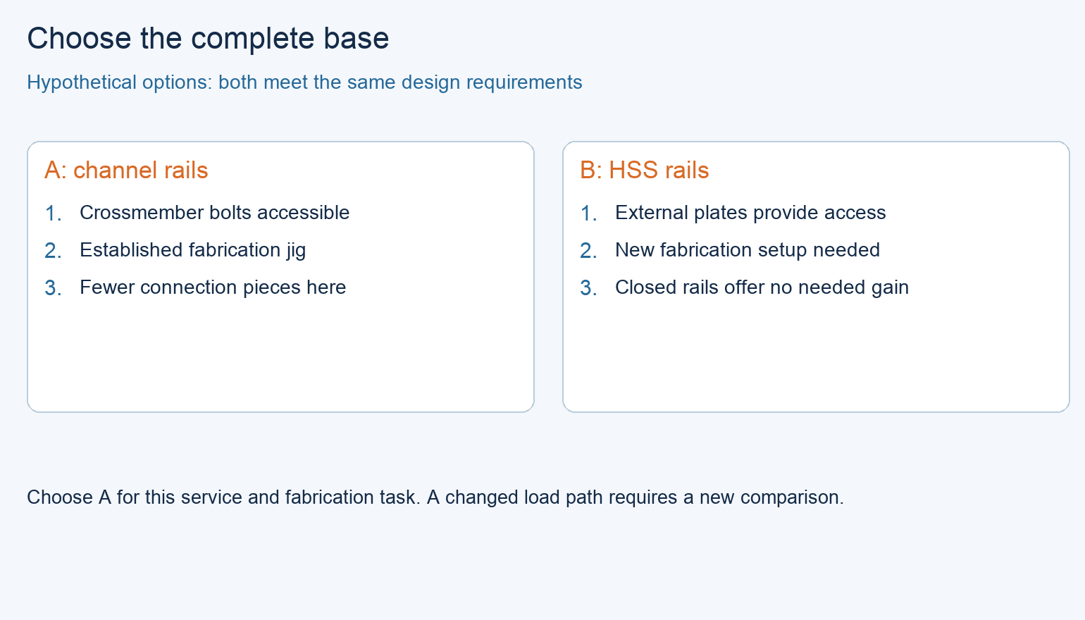
Option A uses channel rails, oriented so the specified crossmember bolts remain accessible. Its pad and restraint details meet the design requirements, and the fabricator has an accepted jig and machining sequence for that arrangement. Option B uses rectangular HSS rails with designed external connection plates. Its bolts are also accessible, but this particular design adds separate fabricated connection plates and a new jig setup. Both fit the equipment envelope and delivery date.
Choose for the Actual Maintenance and Fabrication Task
Choose A for the stated project. It provides the required service access with an already established fabrication method and fewer separate connection pieces in these two offers. The decision is not that channels are always lighter or cheaper, or that HSS cannot be bolted. B remains a technically suitable option; its closed shape provides no decisive benefit for this already-qualified arrangement.
Change the scenario to an offset equipment layout where the revised design develops significant rail twisting and the channel proposal needs extensive additional restraint. Recompare the redesigned bases. HSS can become the preferred starting point if it meets the new movement limits with a simpler complete arrangement. Likewise, if an external service obstruction prevents wrench access, revise the connection layout before releasing either base.
Specify the Complete Skid, Not Just a List of Steel Sizes
Define the Finished Interfaces
The purchase package should identify the accepted assembly drawing, material grades and full section designations, cut lengths, orientation, connection details, mounting-hole pattern and finished mounting-surface requirements. Include the support and lifting arrangements that the design uses. If the supplier is also designing the base, make that design scope explicit before treating a material list as final.
Compare the Same Fabrication Scope
Compare quotations at the same fabrication stage. Bare cut sections, a welded frame and a machined, coated and inspected base are different deliverables. Check whether pads, connection plates, removable hardware, machining and dimensional reporting are included. Do not claim a shape is cheaper from its steel mass alone.
At receipt, compare the finished mounting and support interfaces with the accepted drawing and inspection requirements. Changes to hole locations, supports or section orientation need design review even when the replacement steel has the same nominal weight per length.
Frequently asked questions
Can I select skid steel by equipment weight alone?
No. The locations and directions of reactions, support spans, operating forces and permitted movement determine the load path. Two machines with the same weight can require different bases because their feet, loads and supports differ.
Are two back-to-back channels equivalent to a rectangular tube?
Do not assume equivalence. Their connections determine whether and how they act together, and their torsional behavior depends on the built-up geometry and restraints. Use the actual assembled member in the design rather than adding two catalog properties and calling it a tube.
Can a thicker section solve machine vibration?
It changes stiffness and mass, but does not by itself establish an acceptable response. Recheck the coupled machine-and-support system against the actual excitation and acceptance criteria. Alignment, support conditions and connection flexibility may also matter.
Can equipment feet bolt directly to an HSS wall?
Only when the designed connection is suitable for that wall and the applied loads. Bolt access, wall distortion and local load transfer must be addressed. A designed pad, plate or proprietary fastener arrangement may be needed; drilling through the tube is not an automatic solution.
Should every mounting pad be machined?
Use the equipment’s mounting-surface requirements. Some arrangements need machined faces; others use a different accepted adjustment or support detail. Specify the required finished geometry and inspection method rather than making machining universal or omitting it from a sensitive interface.
Can the operating support points also be used for lifting?
Only if the approved lifting arrangement uses them and the base is checked for that condition. Lifting can change forces, restraints and load paths. Keep lifting points and instructions tied to the actual assembled package, including its center of gravity.
Technical Basis and Source Scope
University of Manchester, Seeing and Touching Structural Concepts, Shear and Torsion, Models 4–6, and Resonance, introductory explanation, checked October 19, 2026. These explain section behavior and dynamic response; their demonstration dimensions and ratios are not skid-design criteria.
Steel Tube Institute, Bolting to HSS Members, Jason Ericksen, May 2014, opening discussion and HSS wall limit states; Connecting Hollow Structural Section Members with Through-Bolts, Jason McCormick, July 2017, wall flexibility discussion. Used for connection mechanisms, not as a claim of compliance with a current code edition. The pump-base comparison is a hypothetical editorial example, not a reported customer project.